
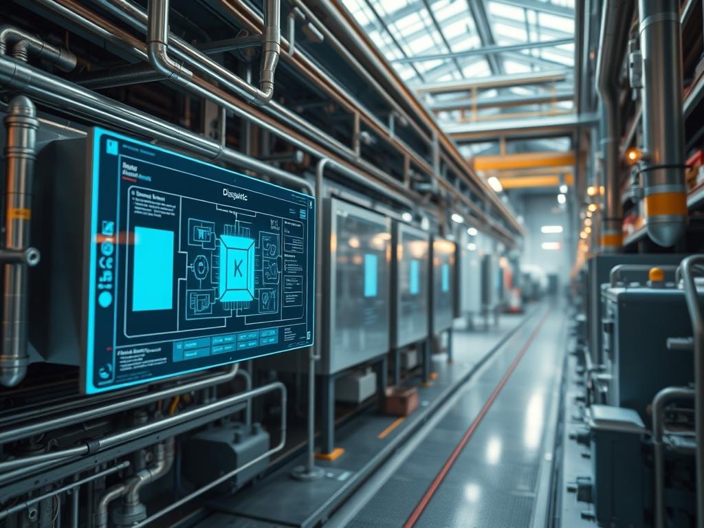
Industrial evaporator defrost logic represents the critical control layer managing the transition between refrigeration cycles and thermal restoration sequences. In industrial environments, such as cold storage or chemical processing, frost accumulation on evaporator fins creates an insulating barrier that increases thermal resistance and reduces air-side throughput. This accumulation leads to a drop in suction pressure and a significant increase in compressor energy consumption. The defrost logic serves as the idempotent governor of this process; it must balance the removal of surface ice against the unintended heat load introduced to the refrigerated space. By comparing electric, hot gas, and air defrost methodologies, systems architects can calculate the specific thermal-inertia and energy payload required for various operational states. This manual defines the integration of these processes within a PLC-driven (Programmable Logic Controller) environment. Effective implementation ensures high-availability infrastructure by mitigating the risk of evaporator freeze-ups and mechanical stress on the compressor rack.
Technical Specifications
| Feature | Requirement | Operating Range | Protocol/Standard | Impact Level | Recommended Resources |
| :— | :— | :— | :— | :— | :— |
| Logic Controller | PLC / PAC | 0 to 60 Celsius | Modbus TCP/IP | 10 | 512MB RAM / 1GHz CPU |
| Temperature Input | RTD / Thermocouple | -50F to +100F | 4-20mA Analog | 9 | PT100 Platinum Grade |
| Hot Gas Pressure | Discharge Gas | 150 to 300 PSI | ASME B31.5 | 8 | Schedule 80 Steel |
| Electric Load | Resistive Heaters | 230V to 480V AC | NEC Article 440 | 7 | Incoloy 800 Sheathing |
| Air Defrost Logic | Logic Gate | > 34F Ambient | BACnet / IP | 4 | Low-Latency Sensors |
| Communications | Shielded Twisted Pair | 10/100 Mbps | IEEE 802.3 | 6 | CAT6 STP |
The Configuration Protocol
Environment Prerequisites:
1. Licensed access to the PLC development environment (e.g., Studio 5000 or TIA Portal).
2. Physical installation of Pressure-Transducers on the suction and discharge headers.
3. Compliance with NEC (National Electrical Code) for high-voltage heating element termination.
4. Firmware version 4.2 or higher for all networked VFD (Variable Frequency Drive) units to ensure compatibility with defrost fan-speed logic.
5. Administrative rights to the SCADA (Supervisory Control and Data Acquisition) interface for setpoint modification.
Section A: Implementation Logic:
The engineering design of defrost logic relies on the concept of thermal equilibrium. Electric defrost utilizes resistive heating elements embedded in the evaporator coil. This method is straightforward but introduces high electrical overhead. Hot Gas defrost redirects high-pressure refrigerant vapor directly from the compressor discharge into the evaporator, turning the evaporator into a condenser. This method provides the highest thermal throughput and efficiency but involves high mechanical complexity; the logic must prevent liquid slugging when the gas condenses. Air defrost, or “Off-Cycle” defrost, simply stops the refrigerant flow while the fans continue to run, utilizing latent heat from the room. It is only viable for rooms above 34 degrees Fahrenheit. Choosing between these involves analyzing the concurrency of the plant load and the available energy payload at the compressor rack.
Step-By-Step Execution
1. Initialize Defrost Trigger Logic
The first step involves defining the criteria for a defrost cycle. Navigate to the PLC_TAG_DATABASE and define the variable DEFROST_INTERVAL. This is usually a timer-based trigger or a demand-defrost trigger based on a differential pressure sensor across the evaporator coil.
System Note: This action establishes the initial entry point in the system kernel. If using demand-defrost, the logic monitors signal-attenuation from the air pressure sensors to determine when frost restricts flow beyond the efficiency threshold.
2. Execute Refrigerant Pump-Down
For both electric and hot gas defrost, the liquid line solenoid must be closed while the fans continue to run. Monitor the SUCTION_PRESSURE_LOW_LIMIT until it reaches the setpoint (typically 5-10 PSI).
System Note: The pump-down cycle clears the evaporator of liquid refrigerant. This prevents the heating energy from being wasted on boiling off standing liquid, reducing the thermal load on the room during the cycle and preventing liquid-hammer in the suction line.
3. De-energize Evaporator Fans
Once the pump-down is verified by the PLC_INPUT_MODULE, send a stop command to the EVAP_FAN_CONTACTOR or an EMS_STOP to the VFD via Modbus.
System Note: Stopping the fans prevents the heat generated during defrost from being circulated into the refrigerated space. This minimizes the temperature spike in the room, maintaining the thermal stability of stored products.
4. Activate Defrost Heating Source
For electric defrost, energize the HEATER_OUTPUT_COIL. For hot gas defrost, energize the HOT_GAS_SOLENOID_VALVE and the REGLATING_PRESSURE_CHECK_VALVE.
System Note: In hot gas mode, this action redirects the refrigerant mass flow. The system kernel must monitor the discharge pressure to ensure it does not drop below the minimum required to move gas through the evaporator. This is a critical point for maintaining throughput in the refrigeration rack.
5. Monitor Termination Parameters
Calibration of the DEFROST_TERMINATION_SENSOR (usually a bulb or RTD attached to the evaporator return bend) is essential. Set the logic to terminate at 50-60 degrees Fahrenheit.
System Note: Using a Fluke-714 or similar calibrator, verify the 4-20mA scaling. Termination is the most important logic gate to prevent “steaming” the evaporator, which deposits moisture on the ceiling and structural components.
6. Implement Drip Time and Fan Delay
After the heating source is disabled, initiate a DRIP_TIMER (usually 5 minutes) followed by a FAN_DELAY. Re-open the liquid line solenoid to allow the coil to chill before the fans restart.
System Note: This step ensures all melted frost has drained into the CONDENSATE_PAN. The fan delay prevents the moisture remaining on the fins from being blown into the room as a mist, which would immediately refreeze on the floors and product.
Section B: Dependency Fault-Lines:
Software conflicts in defrost logic often stem from improper encapsulation of the defrost subroutine. If the master cooling loop does not “handshake” correctly with the defrost module, the compressor may short-cycle. Mechanical bottlenecks include restricted ORIFICE_PLATES in hot gas lines or burnt-out resistive elements. A common failure in electric systems is the failure of the HIGH_LIMIT_SAFETY_SWITCH, which should physically interrupt power regardless of PLC logic if the heater surface exceeds safe temperatures.
THE TROUBLESHOOTING MATRIX
Section C: Logs & Debugging:
Log analysis should focus on the SYS_EVENT_LOG located at /var/log/fridge_logic.log or the internal PLC diagnostic buffer. When troubleshooting, look for specific error strings.
- Error Code 405 (Defrost Timeout): Indicates the termination temperature was not reached within the MAX_DEFROST_TIME setting. CHECK: Inspect heating elements or hot gas solenoid for mechanical failure.
- Error Code 512 (Suction Pressure Low): Occurs during pump-down if the solenoid leaks. CHECK: Use a Leak-Detector on the liquid line valve seat.
- Visual Cue (Ice on Ceiling): This indicates “Steaming”. The termination temperature is set too high, or the DRIP_TIMER is insufficient.
- Visual Cue (Bottom of Coil Frozen): Indicates the DRAIN_LINE_HEATER has failed. Verify current draw on the drain heater circuit using a Clamp-Meter.
OPTIMIZATION & HARDENING
Performance Tuning (Thermal Efficiency):
To optimize the defrost cycle, implement “Demand-Defrost” rather than “Timed-Defrost”. By using an optical sensor or a differential air pressure transducer (DPI_SENSOR_01), the system only initiates a cycle when frost actually exists. This reduces the total energy overhead and prevents unnecessary heating of the refrigerated space. Fine-tune the thermal-inertia by adjusting the hot gas pressure regulator to the lowest effective pressure that clears the ice.
Security Hardening (Fail-safe Physical Logic):
Ensure all defrost outputs are wired through a hardware-based E-STOP and a thermal overload relay. For networked controllers, implement firewall rules to restrict Modbus traffic to the IP_ADDRESS of the authorized HMI. Use Role-Based Access Control (RBAC) on the SCADA system to prevent unauthorized changes to the DEFROST_TERMINATION_SETPOINT.
Scaling Logic:
In large facilities with multiple evaporators, use “Defrost Sequencing” to prevent multiple units from defrosting concurrently. This stabilizes the compressor rack load and prevents huge spikes in electrical demand or discharge pressure drops. The PLC should use a “Queue” logic where only one evaporator per rack branch can enter a defrost state at any given time.
THE ADMIN DESK
Q: Why is my room temperature spiking 10 degrees during defrost?
Check if the evaporator fans are spinning during the cycle. The logic should ensure the FAN_OUTPUT is disabled. Alternatively, the MAX_DEFROST_TIMER may be too long, or the termination sensor is poorly positioned, causing excessive heat injection.
Q: Can I use air defrost for a 0-degree freezer?
No; air defrost requires an ambient temperature higher than the freezing point of water. In a freezer, air defrost will fail to melt the ice and will likely contribute to further frost through moisture migration from the fans.
Q: What if the hot gas solenoid vibrates loudly?
This is often caused by gas velocity or slugging. Ensure the logic includes a proper pump-down to clear liquid before the hot gas enters. Also, check the GAS_REGULATOR settings to ensure the pressure differential is within the manufacturer’s specification.
Q: How do I verify if an electric heater is failing?
Use a Multi-Meter to check the resistance (Ohms) of each element. Compare the reading to the specification on the evaporator nameplate. An “Open” reading indicates a broken element; a “Short” to ground indicates insulation breakdown in the Incoloy sheath.
Q: Is Modbus or Ethernet/IP better for defrost control?
Ethernet/IP offers faster latency and easier integration with modern AOIs (Add-On Instructions). Modbus is more universal for older hardware. For critical safety-related defrost logic, hard-wired interlocks are always preferred over network protocols.