
Building Envelope Air Pressure serves as the foundational regulatory mechanism for managing the stack effect in high-rise structures and complex industrial facilities. This phenomenon refers to the vertical movement of air driven by buoyancy and density differentials between internal and external environments. In the technical stack of modern smart-building infrastructure, Building Envelope Air Pressure acts as the buffer layer between thermal-inertia and external environmental variables. If left unmanaged, the stack effect causes excessive “throughput” of air via elevator shafts and stairwells; this leads to mechanical failure of door systems, increased energy “overhead,” and the potential for moisture infiltration. To mitigate these risks, architects must implement a robust control strategy that treats the building enclosure as a pressurized vessel, utilizing automated systems to maintain a neutral or slightly positive pressure relative to the exterior atmosphere.
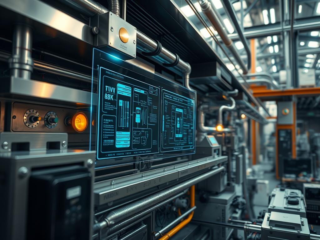
TECHNICAL SPECIFICATIONS
| Requirement | Default Operating Range | Protocol / Standard | Impact Level | Recommended Resources |
| :— | :— | :— | :— | :— |
| Differential Pressure | 0.05 to 0.15 in. w.g. | ASHRAE 62.1 / 90.1 | 9 | High-Accuracy Transducers |
| Air Exchange Rate | 0.5 to 2.0 ACH | LEED / WELL Standard | 7 | VFD-driven AHUs |
| Network Integration | 38.4 kbps to 115.2 kbps | BACnet MS/TP or IP | 8 | Cat6 / RS-485 Shielded |
| Response Latency | < 500ms | IEEE 802.3 | 6 | 1GHz+ CPU Logic |
| Envelope Permeability | < 0.25 L/s per m2 | ASTM E779 | 10 | Closed-Cell Polyurethane |
THE CONFIGURATION PROTOCOL
Environment Prerequisites:
1. Integration with Global Controller (GC) or Building Management System (BMS) running firmware version 4.8 or higher.
2. Installation of Differential Pressure Transducers at the building baseline (Grade), mid-point, and parapet levels.
3. Adoption of IEEE 802.3 Ethernet standards for all networked sensor nodes to minimize signal-attenuation over long vertical runs.
4. NEC Class 2 wiring for all low-voltage control circuits to prevent thermal-overload.
Section A: Implementation Logic:
The engineering logic for managing Building Envelope Air Pressure revolves around the concept of active volume compensation. The stack effect is a density-driven process: warm air rises, creating a vacuum at the base (negative pressure) and a surplus at the crown (positive pressure). By treating the building as a controlled “payload” of air, we can use Variable Frequency Drives (VFDs) on the Supply Fans (SF) and Return Fans (RF) to modulate the internal mass balance. We utilize a Proportional-Integral-Derivative (PID) loop to ensure that the response is idempotent; every change in outdoor temperature must trigger a repeatable and precise change in fan speed to maintain the pressure set-point. This prevents the “hunting” behavior that characterized legacy pneumatic systems and reduces mechanical wear on the dampers.
Step-By-Step Execution
1. Initialization of the Reference Pressure Baseline
Mount an external reference tube at the building’s neutral pressure plane, typically located at 50 percent of the total height. Connect this to the high-port of the Master Pressure Transducer.
System Note: This establishes the hardware-level “Zero Point.” Failure to properly shield the external probe from wind gust “noise” will result in erratic throughput calculations at the BMS level.
2. Implementation of PID Control Loops
Access the Field Controller via the command line or GUI and define the logic for the Supply Fan modulation. Set the Target Setpoint (SP) to +0.10 in. w.g.
System Note: This modifies the firmware-level control sequence by adjusting the Analog Output (AO) voltage to the VFD. This action directly influences the thermal-inertia of the floor plates by stabilizing the air mass.
3. Verification of Signal Integrity via RS-485
Use a fluke-multimeter to check the voltage across the BACnet MS/TP terminals. Ensure the resistance is exactly 120 ohms at the end-of-line (EOL) resistors.
System Note: Proper termination prevents “Reflected Waves.” In high-rise environments, signal-attenuation can occur if the trunk length exceeds 1,200 meters, leading to packet-loss in the sensor telemetry.
4. Integration of Stairwell Pressurization Fans
Execute the systemctl restart bms-service command (or its vendor-specific equivalent) after mapping the stairwell fire-alarm contacts to the building’s air pressure logic.
System Note: This step ensures the “Safety Kernel” of the building is active. Upon a fire signal, the fans must immediately reach maximum throughput to prevent smoke encapsulation within egress paths.
5. Deployment of Perimeter Sealant and Air Barriers
Apply high-performance vapor-permeable membranes to all Building Envelope penetrations. Use a thermal-imaging camera to detect “leaks” which equate to “unauthorized data packets” in our air pressure stack.
System Note: Physical sealing reduces the “load” on the digital control system. It minimizes the overhead required by the VFDs to maintain the desired pressure gradient.
Section B: Dependency Fault-Lines:
The most common bottleneck in maintaining Building Envelope Air Pressure is the “Open Door Latency.” When main lobby doors are held open, the sudden drop in pressure creates a massive intake of outside air; this is the mechanical equivalent of a Distributed Denial of Service (DDoS) attack on the HVAC system. Another fault-line is the “Sensor Drift” associated with humidity. High moisture content can cause signal-attenuation at the transducer diaphragm, leading to false readings and incorrect concurrency between the supply and exhaust cycles.
THE TROUBLESHOOTING MATRIX
Section C: Logs & Debugging:
When the system indicates a “Pressure Variance Fault” (Error Code: E-PRESS-0402), the architect must perform a packet trace on the BACnet trunk. If the log shows high latency in sensor updates, check the physical wiring for electromagnetic interference (EMI).
1. Check Log Path: /var/log/bms/pressure_audit.log
2. Review Sensor Readout: If the value is static at 32767, the encapsulation of the analog signal has failed (likely a broken wire).
3. Audit VFD Frequency: Use the vfd-status –all command to ensure the fan is not stuck in a “Bypass” state.
4. Visual Indicator: If the “Whistle Effect” is heard at the elevator doors, the Building Envelope Air Pressure is excessively positive at the top or negative at the bottom. Adjust the Offset Variable in the Site Configuration File.
OPTIMIZATION & HARDENING
– Performance Tuning: To improve throughput efficiency, implement “Predictive Control” based on weather forecasts. If the system knows a cold front is arriving, it can pre-pressurize the building to counteract the coming increase in stack effect. This manages the thermal-inertia more effectively than reactive PID loops.
– Security Hardening: Ensure that the BACnet gateway is behind a dedicated firewall. Disable unnecessary protocols like Telnet or HTTP on the field controllers. Use strong passwords for the Admin Console to prevent unauthorized set-point manipulation. Secure the physical sensor housings with tamper-proof screws.
– Scaling Logic: As the building expands or internal floor use changes (e.g., converting office space to a data center), update the Air Pressure Map. Add more nodes to the BACnet network to increase the granularity of the data. Use a “Master-Slave” fan configuration to handle higher loads without increasing the latency of the control response.
THE ADMIN DESK
How do I fix a persistent negative pressure alarm at the ground floor?
Check for “Short-Circuiting” of air through the elevator shafts. Ensure the penthouse louvers are closing correctly. Increase the VFD frequency of the ground-floor Outside Air (OA) units to inject more mass into the lower levels.
What causes high latency in the pressure sensors?
This is often due to “Line Noise” or excessive “Daisy-Chaining” on the RS-485 trunk. Ensure that no more than 32 devices are on a single segment and that the cable is shielded twisted-pair.
Can the stack effect be used for passive cooling?
Yes; by carefully modulating the Building Envelope Air Pressure, you can create a “Solar Chimney” effect. However, this requires precise concurrency between motorized windows and exhaust fans to prevent uncontrolled heat gain.
Why is my pressure transducer showing 0.00 even when fans are on?
Verify the “Reference Tube” is not clogged with debris or ice. If the sensor can’t compare internal air to external air, the payload calculation will always return a null value.
What is the impact of envelope leaks on fan lifespan?
Constant leakage forces the VFDs to run at high frequencies with high concurrency. This increases the “Duty Cycle” of the motors, leading to premature bearing failure and increased maintenance overhead.