
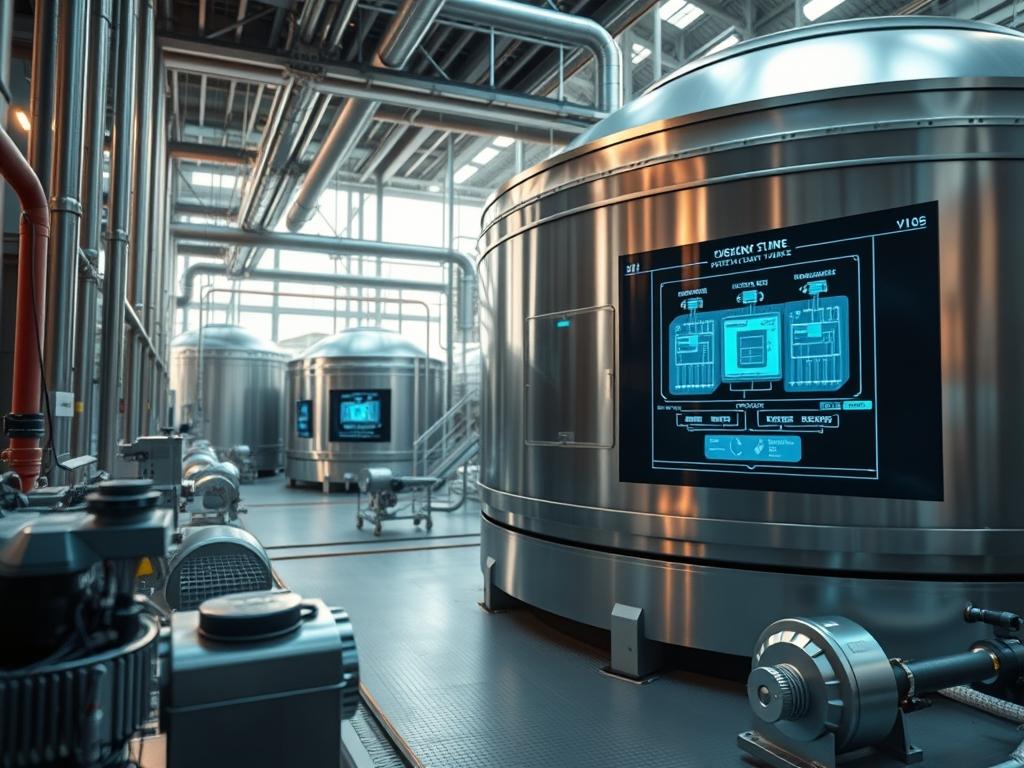
Thermal Energy Storage Tanks serve as the critical physical buffer within modern hydronic, district energy, and data center cooling infrastructures. Functioning effectively as thermal capacitors, these vessels decouple energy generation from demand, allowing for peak-shaving and significantly reduced operational expenditure. In the context of a modern technical stack, such as a Tier IV data center or a large-scale district cooling plant, the Thermal Energy Storage Tanks act as the fail-safe layer that maintains environmental stability when primary chillers face high latency or hardware failure. The core problem addressed by these systems is the temporal mismatch between energy availability and consumption. By storing chilled or heated water during off-peak hours, the system optimizes the throughput of the central plant. This solution requires precise engineering of sizing and insulation to minimize thermal decay and maximize the thermocline stability, ensuring that energy remains available with minimal loss over extended durations.
Technical Specifications
| Requirement | Default Port/Operating Range | Protocol/Standard | Impact Level (1-10) | Recommended Resources |
| :— | :— | :— | :— | :— |
| Structural Integrity | -20F to 200F | ASME Section VIII | 10 | Carbon Steel / SS304 |
| Thermal Stratification | 0.5 to 1.5 ft/min | ASHRAE 90.1 | 8 | Radial Diffusers |
| Insulation R-Value | R-15 to R-30 | ASTM C518 | 9 | Polyisocyanurate |
| Logic Interface | Port 502 (Modbus) | Modbus TCP/BACnet | 7 | PLC / Logic Controller |
| Sensor Accuracy | +/- 0.1 degree C | NIST Traceable | 6 | PT1000 RTD Sensors |
| Vapor Encapsulation | 0.02 Perms | ASTM E96 | 9 | Aluminum Jacket |
THE CONFIGURATION PROTOCOL
Environment Prerequisites:
Successful deployment of Thermal Energy Storage Tanks requires strict adherence to physical and digital prerequisites. Physically, the installation site must comply with ASME Section VIII for pressure vessels or AWWA D100 for atmospheric tanks. Historically, foundations must support the massive static load of the fluid payload without subsidence. Digitally, the integration layer requires a logic-controller (e.g., Schneider Electric M340 or Siemens S7-1500) with firmware versions supporting Modbus TCP or BACnet/IP. Field technicians must possess EPA 608 certification for refrigerant handling if the tank is integrated into a direct-expansion loop, and all electrical terminations must follow NEC Article 430 for motor-operated valves.
Section A: Implementation Logic:
The engineering design of Thermal Energy Storage Tanks rests on the principle of buoyancy-driven stratification. Rather than mixing warm and cold medium, the system relies on the density differential of water at varying temperatures to create a thermocline: a narrow horizontal band across which temperature changes rapidly. High thermal-inertia is the goal; the tank must resist rapid temperature shifts caused by internal turbulence. To achieve this, the inlet and outlet velocities must be strictly governed to maintain a low Froude number, ensuring that the payload of energy is delivered with minimal signal-attenuation (thermal mixing). Proper sizing ensures the plant can sustain the maximum cooling or heating load (throughput) for the duration of the peak utility window.
Step-By-Step Execution
1. Calculate Peak Thermal Load and Volume
Determine the total energy requirement in Ton-Hours or Megajoules. The formula V = Q / (rho Cp delta-T) defines the required volume where Q is the total heat capacity and delta-T is the usable temperature range.
System Note: This action sets the physical boundaries for the hardware. Over-sizing leads to excessive overhead and unnecessary capital expenditure; under-sizing results in a latency issue where the system cannot meet peak demand.
2. Determine Tank Geometry for Stratification
Select an aspect ratio (Height-to-Diameter) between 2:1 and 4:1. This verticality encourages the formation of a stable thermocline.
System Note: A tall, slender geometry reduces the surface area of the mixing layer. Using fluent-cfd or similar modeling software, simulate the flow to ensure that the internal concurrency of water layers remains undisturbed during high-flow events.
3. Install Radial Diffuser Arrays
Mount internal diffusers at the top and bottom of the tank. These components must distribute the fluid horizontally to prevent vertical “jetting” which destroys stratification.
System Note: High-velocity injections act as noise in a physical system. The diffusers function as a low-pass filter, ensuring that the kinetic energy of the incoming fluid does not disrupt the thermal-inertia of the stored volume.
4. Apply Rigid Board Insulation and Vapor Barrier
Install high-density polyisocyanurate or mineral wool boards directly to the tank exterior using adhesive-pins. Ensure all joints are staggered to prevent thermal bridging.
System Note: This is the physical encapsulation layer. Poorly sealed joints allow for moisture ingress, leading to Corrosion Under Insulation (CUI). Use a global fluke-ti400 thermal imager to verify the integrity of the insulation envelope after application.
5. Deploy the Sensor Matrix and Logic Controller
Install a vertical string of PT1000 RTD sensors at 1-foot intervals along the tank height. Connect these to the logic-controller via shielded twisted-pair cabling to minimize signal-attenuation.
System Note: The PLC must execute an idempotent polling routine to calculate the current State of Charge (SoC). Execute systemctl restart bms-gateway to ensure the updated registers are visible to the broader Building Management System.
Section B: Dependency Fault-Lines:
The most common failure in Thermal Energy Storage Tanks is “Thermocline Collapse.” This occurs when the domestic water supply pressure is unstable or when the pumping logic causes a sudden surge in velocity. If the logic-controller fails to modulate the VFD (Variable Frequency Drive) correctly, the resulting turbulence acts as a massive packet-loss event for the stored thermal energy, mixing the entire tank into a lukewarm, unusable state. Another bottleneck is “Vapor Barrier Breach.” In chilled water applications, if the outer jacket is not airtight, ambient humidity will migrate toward the cold tank surface, condense, and saturate the insulation; this drastically increases thermal conductivity and can lead to structural failure through rapid oxidation.
THE TROUBLESHOOTING MATRIX
Section C: Logs & Debugging:
When diagnosing efficiency drops, first examine the temperature gradient logs. Access the BMS logs at /var/log/bms/thermal_trace.log or via the PLC web interface.
- Error Code 0xST-FAIL (Stratification Failure): If the sensors indicate a temperature delta of less than 2 degrees C across the middle 50% of the tank during a discharge cycle, the diffuser may be dislodged or the flow rate has exceeded the design threshold. Verify the modbus-register 40012 for current flow GPM.
- Error Code 0xVB-BREACH (Vapor Barrier Breach): Visual cue: Ice formation on the outer cladding or dripping water from bottom insulation seams. Use a sensirion-humidity-probe to check for moisture levels behind the metal jacket at the base of the tank.
- Sensor Drift/Packet-Loss: If the logic-controller reports erratic temperature spikes (e.g., jumping from 40F to 150F in one second), check for electromagnetic interference (EMI) on the sensor leads or a loose terminal at the analog-input-module.
OPTIMIZATION & HARDENING
Performance Tuning
To improve thermal efficiency, implement a “Predictive Dispatch” algorithm within the logic-controller. By integrating a weather forecast API, the system can adjust the throughput of the charging cycle based on the predicted peak of the following day. This reduces unnecessary chiller cycles and minimizes the overhead of keeping the tank at minimum temperature during cooler days. Ensure the PID loops for the mixing valves have a slow ramp-up time to prioritize the stability of the thermocline over immediate response latency.
Security Hardening
Physical security involves locking all manway hatches and sensor junction boxes to prevent tampering. At the network level, the logic-controller must be isolated on a dedicated OT (Operational Technology) VLAN. Disable all unused services such as Telnet or HTTP in favor of SSH and HTTPS. Implement firewall rules that only allow traffic between the tank’s PLC and the primary BMS server. Regularly audit the chmod permissions on the BMS configuration files to ensure only “admin” level users can modify the thermal setpoints.
Scaling Logic
When expanding the capacity, a modular “Tank Farm” approach is superior to a single massive vessel. Connect multiple Thermal Energy Storage Tanks in a parallel configuration using a common header. This allows for concurrency in maintenance; one tank can be taken offline for inspection via systemctl stop tank-node-1 without interrupting the thermal supply to the facility. This “Array of Independent Tanks” strategy ensures high availability and allows the system to scale linearly with the growth of the data center or hospital campus.
THE ADMIN DESK
Q1: How do I calculate the State of Charge (SoC)?
The SoC is the ratio of stored thermal energy to total capacity. Use the logic-controller to average the readings of the sensor string and compare them against the design delta-T. An SoC of 1.0 indicates a fully charged tank.
Q2: What is the primary cause of thermal decay?
Thermal decay is usually caused by thermal bridging through tank supports or pipe penetrations. Ensure all “cold-shoe” supports are thermally isolated from the tank shell to prevent the payload from leaking into the foundation.
Q3: How often should I calibrate the RTD sensors?
Sensors should be calibrated annually using a dry-well calibrator. Check the log at /etc/thermal/cal_history.csv to ensure the offset values remain within the NIST-traceable tolerance of +/- 0.1 degree C.
Q4: Can I use this setup for both heating and cooling?
Yes, but the density inversion of water at 39.2F (4C) must be accounted for in the logic. For heating, the hot water is stored at the top; for cooling, the cold water stays at the bottom.
Q5: What happens if the thermocline is lost?
If the thermocline collapses, the tank loses its ability to deliver consistent temperatures. The system must “Reset” by fully charging or discharging the tank at a very low flow rate to re-establish the density layers.