
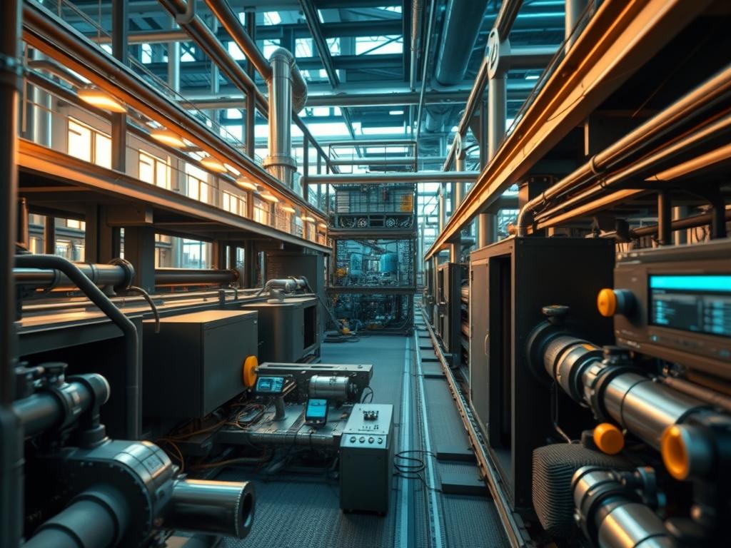
Automating the extraction and transport phases within Biomass Ash Management Systems is a critical requirement for modern energy infrastructure. These systems function as the terminal stage of the biomass combustion cycle; they are responsible for the removal of both bottom ash and fly ash payloads from the boiler and filtration units. In high-output environments, manual ash handling introduces significant latency and operational hazards. By integrating automated logic controllers and sensor arrays, the system achieves a higher throughput while maintaining thermal-inertia stability within the primary combustion chamber. The problem resides in the accumulation of ash which acts as a thermal insulator; if not removed at a rate proportional to fuel consumption, it degrades the heat transfer efficiency to the water-wall tubes. The solution detailed in this manual involves an idempotent control sequence that synchronizes the mechanical removal assets with the real-time combustion metrics of the plantSCADA (Supervisory Control and Data Acquisition) network.
Technical Specifications
| Requirement | Default Port/Operating Range | Protocol/Standard | Impact Level | Recommended Resources |
| :— | :— | :— | :— | :— |
| PLC Logic Controller | Port 502 (Modbus TCP) | IEC 61131-3 | 10 | 1.2GHz Dual-Core ARM / 2GB RAM |
| Ash Level Sensors | 4-20mA Current Loop | HART Protocol | 8 | IP67 Rated Enclosure |
| Conveyor VFDs | Port 44818 (EtherNet/IP) | IEEE 802.3 | 7 | Heavy-Duty Material Grade |
| Thermal Monitoring | -40 to 1200 Celsius | Type K Thermocouple | 9 | Stainless Steel Thermowell |
| Network Gateway | Port 80/443 | TLS 1.3 / MQTT | 6 | Industrial Grade Firewall |
The Configuration Protocol
Environment Prerequisites:
Successful implementation requires adherence to several industrial standards and hardware baselines. The system must comply with NEC Article 70 for electrical safety and ISA-95 for enterprise-to-control system integration. All Logic-Controllers must run firmware version 4.0 or higher to support the necessary concurrency in multi-threaded task execution. Technicians must possess root-level access to the HMI (Human-Machine Interface) and administrative permissions for the PLC (Programmable Logic Controller) backplane. Ensure that the Physical-Layer cabling is shielded (Cat6A or higher) to prevent signal-attenuation in high-voltage environments typical of power generation facilities.
Section A: Implementation Logic:
The engineering design relies on the principle of load-proportional extraction. Instead of a simple timer-based trigger, the system calculates the frequency of ash removal based on the payload of biomass fuel entering the combustion chamber. This creates an idempotent process where the command to “Clear Ash” only executes if the sensor feedback confirms a specific accumulation threshold. This design minimizes the mechanical overhead on motor starters and reduces the thermal-inertia disturbance caused by opening air-locked valves. By decoupling the removal cycle from rigid schedules and moving toward a data-driven trigger, the system reduces the risk of packet-loss in the feedback loop causing a mechanical overflow.
Step-By-Step Execution
1. Initialize Peripheral Sensor Arrays
Interface with the Logic-Controller via a secure terminal or the engineering workstation. Configure the AI_01 through AI_08 (Analog Input) ports to receive the 4-20mA signals from the ultrasonic ash level sensors located in the hopper.
System Note: This action initializes the hardware-level drivers for the sensor suite; it maps the physical voltage into a 16-bit integer within the controller memory, allowing the kernel to process physical depth as a digital value.
2. Configure VFD Frequency Parameters
Access the Frequency-Inverter settings via the Modbus-TCP bridge. Set the Max_Hz to 60 and the Acceleration_Ramp to 5 seconds to manage the torque demands of heavily loaded conveyors.
System Note: This step modulates the power-stage of the motor controller; it prevents instantaneous current spikes that could trigger a thermal-overload trip on the main circuit breaker.
3. Establish Network Encapsulation
Define the VLAN (Virtual Local Area Network) parameters on the industrial switch to isolate the Biomass Ash Management Systems traffic from the general corporate network. Use IEEE 802.1Q tagging to prioritize the SCADA packets.
System Note: Encapsulation ensures that control commands are not delayed by non-essential traffic; it minimizes latency and prevents jitter in the time-sensitive feedback loops.
4. Deploy the Logic Script
Load the control logic onto the PLC-CPU. Use the command plc-load -p /path/to/binary or the manufacturer-specific deployment tool. Ensure the Run-Mode switch is set to the authorized position.
System Note: The deployment overwrites the volatile memory of the controller with the new instruction set; it resets the internal task-timer and re-aligns the asynchronous I/O polling cycle.
5. Verify Interlock Status
Test the Emergency-Stop and Safety-Interlock circuits. Use a fluke-multimeter to verify that the logic high (24VDC) is dropped to 0VDC when the physical stop button is depressed.
System Note: This validates the hardware-level fail-safe logic; it ensures the Logic-Controller cannot override physical safety boundaries during a firmware hang or software exception.
Section B: Dependency Fault-Lines:
Software dependencies in industrial environments often center on firmware compatibility and communication drivers. A common failure point is the mismatch between the EDS (Electronic Data Sheet) files and the actual hardware revision of the VFD (Variable Frequency Drive). If the versions do not align, the Logic-Controller may experience packet-loss or fail to recognize the drive on the network. Mechanically, the primary bottleneck is the Rotary-Valve tolerance. If the ash payload contains high moisture levels, the material can bridge across the valve, leading to a “no-flow” condition despite the motor being energized. This creates a feedback loop conflict where the sensor reports high levels, the controller commands removal, but the physical throughput remains zero.
THE TROUBLESHOOTING MATRIX
Section C: Logs & Debugging:
When the system encounters an error, the first point of audit is the Syslog located at /var/log/industrial/ash_manager.log on the gateway device. Look for the “E-404: Node Disconnected” string, which indicates a loss of concurrency between the controller and the remote I/O. If a sensor fails, the SCADA interface will display a “Bad Quality” flag: check the physical terminal block for signs of corrosion or loose wiring that may cause signal-attenuation.
For mechanical faults, specific codes are generated by the VFD. An “F-01 Overcurrent” fault usually points to a physical blockage in the Screw-Conveyor. In such cases, the diagnostic path involves reversing the motor phase momentarily through the HMI manual-override screen to clear the obstruction. Always verify the heartbeat-packet frequency in the network settings; if the latency exceeds 50ms, the system will trigger an automatic safe-shutdown to prevent unmonitored operation.
OPTIMIZATION & HARDENING
Performance Tuning: To increase throughput, technicians should implement a staggered start sequence for the transport chain. Starting the distal conveyor five seconds before the proximal conveyor prevents the “piling” effect. This manages the concurrency of the physical mass movement. Furthermore, adjusting the VFD frequency based on the moisture-content sensors can optimize power consumption and prevent mechanical strain.
Security Hardening: The Biomass Ash Management Systems must be isolated by a stateful firewall. Enable MAC-Address filtering on the switch ports to prevent unauthorized device injection. All Logic-Controller access should require LDAP (Lightweight Directory Access Protocol) authentication if hosted on an integrated network. Disable all unused ports such as Telnet or unencrypted HTTP to shrink the attack surface.
Scaling Logic: To expand the system for additional boiler units, utilize a master-slave architecture. The primary Logic-Controller handles the global payload calculation, while local micro-controllers manage the idempotent execution of specific ash gates. This distributed approach prevents a single point of failure and reduces the communication overhead on the primary industrial backbone.
THE ADMIN DESK
How do I clear a ‘stuck’ rotary valve remotely?
Access the HMI-Manual-Mode. Pulse the Reverse-Contact for two seconds, then return to Forward-Drive. If the current draw remains above the Normal-Threshold, a physical inspection for clinker formation is required to prevent motor burnout.
What causes frequent ‘Packet-Loss’ in the ash circuit sensors?
This is typically caused by electromagnetic interference from high-voltage cables. Ensure all Signal-Cables are routed through dedicated grounded conduits and that the Shield-Drain wire is connected only at the controller end to prevent ground loops.
Why is the ‘Thermal-Inertia’ fluctuating after automation?
Check the Air-Lock seal timing. If the ash removal gates stay open too long, excess secondary air enters the boiler, cooling the bed. Adjust the Close-Delay variable in the logic script to ensure airtight operation.
How often should the ultrasonic sensor be calibrated?
Perform a calibration every 2,000 operational hours or after a significant change in biomass fuel type. Dust buildup on the sensor face can increase signal-attenuation, leading to false “Full” readings in the ash hopper.
Can I update the logic script while the system is running?
Only if the PLC supports “Online Editing”. However, it is safer to wait for a scheduled maintenance window. An idempotent logic update requires a full state-check, which may momentarily disrupt the concurrency of the conveyor motors.