
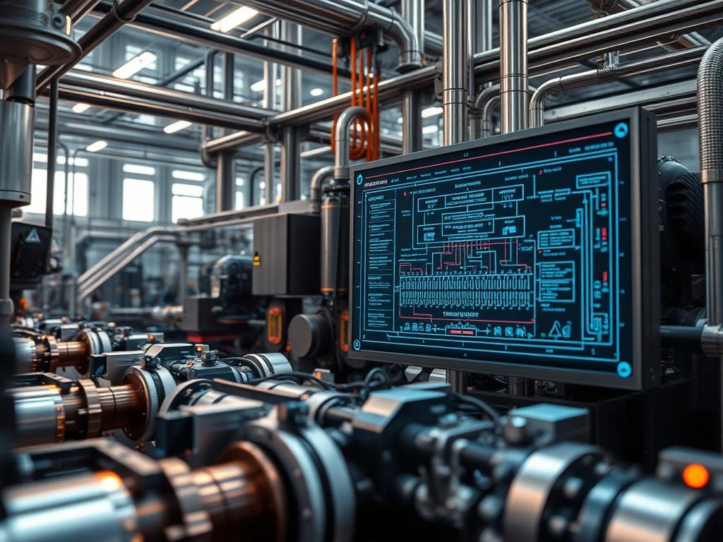
Hydrogen Burner Flame Stability represents the critical equilibrium between the reactant flow velocity and the laminar flame speed within high-output combustion chambers. Unlike conventional hydrocarbon fuels like methane, hydrogen exhibits a significantly higher burning velocity and a vastly lower ignition energy threshold. This introduces a specific set of engineering challenges regarding flashback prevention and blowout mitigation. Within the technical stack of modern energy infrastructure, stable hydrogen combustion is essential for reducing carbon intensity while maintaining thermal throughput. The problem arises from the wide flammability limits of hydrogen; this characteristic can lead to unstable flame anchoring or acoustic oscillations if the fuel-to-air ratio is not precisely regulated. Achieving stability requires an integrated approach involving high-speed sensors, low-latency control logic, and advanced material science. This manual details the architectural requirements and configuration protocols necessary to maintain flame integrity under varying load conditions, ensuring that the hydrogen energy payload remains contained and efficient throughout the operational lifecycle.
TECHNICAL SPECIFICATIONS
| Requirement | Default Port/Operating Range | Protocol/Standard | Impact Level (1-10) | Recommended Resources |
| :— | :— | :— | :— | :— |
| Fuel Feed Pressure | 0.5 to 4.0 Bar | ISO 23551-1 | 9 | SS316L Schedule 80 Piping |
| Control Logic Latency | < 10ms | IEC 61131-3 | 10 | PLC with High-Speed I/O |
| Flame Monitoring | 200nm to 280nm (UV) | NFPA 85 | 8 | UV Flame Scanner |
| Flashback Arrestor | Maximum flow > 150% | EN ISO 5175-1 | 10 | Sintered Stainless Steel |
| Air-Fuel Ratio (λ) | 1.0 to 2.5 | Stoichiometric Control | 7 | O2 Zirconia Sensor |
| Network Telemetry | Port 502 (Modbus/TCP) | IEEE 802.3 | 6 | Cat6e Shielded / 1Gbps |
THE CONFIGURATION PROTOCOL
Environment Prerequisites:
Successful deployment requires an environment compliant with NFPA 2 (Hydrogen Technologies Code) and NEC Class I, Division 2 specifications for hazardous locations. The systems architect must ensure that all logical controllers are running Firmware Version 4.2.0 or higher to support advanced sub-millisecond interrupts. Administrative access to the Human-Machine Interface (HMI) and the Programmable Logic Controller (PLC) backend is mandatory. All hardware interfaces must be grounded to mitigate static discharge: a critical failure point given the low ignition energy of the hydrogen payload.
Section A: Implementation Logic:
The engineering design focuses on overcoming the high reactivity of hydrogen by managing the chemical kinetics and fluid dynamics in real time. The primary logic involves a feed-forward control loop where the fuel supply pressure is modulated based on the measured air mass flow rate to maintain an idempotent combustion state. Because hydrogen flames lack luminosity in the visible spectrum, ultraviolet (UV) or ionization sensors must be used to verify flame presence. The logic must also account for the thermal-inertia of the burner head components: sudden changes in load can cause rapid temperature shifts that degrade material integrity or induce thermal NOx formation. By analyzing the frequency of acoustic emissions within the burner, the controller can preemptively adjust the flow before reaching a resonance state that compromises stability.
Step-By-Step Execution
Step 1: Hydrogen Supply Manifold Pressurization
Ensure the Main_H2_Isolation_Valve is closed before initiating a pressure test of the Hydrogen_Manifold. Utilize a Fluke-718 pressure calibrator to verify that the Pressure_Transmitter_PT101 registers zero. Gradually open the supply to reach a baseline of 2.0 Bar.
System Note: This action establishes the baseline throughput potential for the system. The Kernel_I/O_Manager in the controller monitors the rise time to detect leaks: if the pressure delta does not meet the expected curve, the Safety_Instrumented_System (SIS) will trigger a Category 0 stop.
Step 2: PID Controller Loop Initialization
Configure the PID_Loop_H2_Flow by setting the proportional gain to 1.2, the integral time to 0.5 seconds, and the derivative time to 0.05 seconds. Access the controller via the terminal using ssh admin@192.168.10.50 and navigate to /etc/burnertrol/pid.conf to update these variables.
System Note: Setting these values reduces control latency and prevents hunting. Large oscillations in the control valve can lead to flame lift-off or flashback; the derivative component helps dampen the system response to sudden air-flow fluctuations.
Step 3: UV Flame Scanner Calibration
Mount the UV_Scanner_Type_4 on the burner sight glass and align it with the primary combustion zone. Execute the command ./check_flame_signal –gain=80 to verify signal strength. The output signal must remain above 4.0mA to indicate a healthy flame.
System Note: High temperatures cause ultraviolet signal-attenuation: precise alignment is necessary to overcome signal noise. The Scanner_Logic_Service applies signal encapsulation to the data before sending it to the SIS, ensuring that interference from high-frequency ignition transformers does not cause a false flame-out signal.
Step 4: Actuator Synchronization
Perform a stroke test on the Air_Damper_Actuator and the H2_Control_Valve simultaneously to verify synchronization. Use the Modbus_Command_0x06 to write to Register_40001 and Register_40005. Both components must reach 100 percent open within 3.0 seconds.
System Note: Mismatched timing between air and fuel delivery creates a momentary rich or lean pocket. This increases the logical overhead of the safety system as it must compensate for transients, potentially leading to a lockout if the stoichiometry deviates beyond the 20 percent margin.
Section B: Dependency Fault-Lines:
The most common mechanical bottleneck occurs in the response time of the fuel control valve: if the valve stiction exceeds 1 percent, the resulting flow ripples will induce flame oscillation. Furthermore, network packet-loss in the fieldbus can delay the flame-out signal to the Master_Logic_Controller, resulting in an unburned fuel accumulation. From a library perspective, ensure that the libmodbus version is compatible with the PLC_Runtime_Environment; version mismatches often lead to data corruption in the floating-point registers used for mass flow calculations.
THE TROUBLESHOOTING MATRIX
Section C: Logs & Debugging:
When a stability failure occurs, first examine the system log located at /var/log/burner/safety_stack.log. Look for Error_Code_E04 (Flashback Detected) or Error_Code_E07 (Flame Signal Lost).
- Error_E04: Locate the physical flashback arrestor and check for thermal discoloration. If the Thermal_Fuse_TF1 has tripped, the entire manifold must be purged with nitrogen before a reset is attempted.
- Error_E07: Check the UV scanner lens for carbon build-up or moisture. Use a Multimeter to measure the voltage across Terminal_J12: a reading below 12V indicates a power supply failure or heavy signal-attenuation in the cabling.
- Unstable_Throughput: If the burner exhibits periodic pulsing, investigate the air-supply fan for vfd hunting. Check the VFD_Parameter_201 to ensure the carrier frequency is set high enough to avoid resonance with the burner geometry.
Visual cues from the HMI flame-graph are critical: a “ragged” signal indicates turbulence at the burner head, while a “dropping” signal suggests the flame is moving away from the scanner focal point due to excessive air velocity.
OPTIMIZATION & HARDENING
Performance Tuning:
To maximize thermal throughput, implement a cross-limiting control strategy. This ensures that the air flow leads the fuel flow during a load increase and trails the fuel flow during a load decrease. This logic maintains a lean condition, preventing the high-temperature spikes that lead to NOx formation. Reducing the control cycle time to 5ms will further increase the stability margin by narrowing the window for acoustic feedback loops to develop.
Security Hardening:
Protect the combustion control network by implementing strict firewall rules on the Industrial_Gateway. Allow only TCP Port 502 for Modbus traffic and TCP Port 22 for SSH from authorized MAC addresses. Disable all unused services on the PLC to reduce the attack surface. Physically, ensure that the Manual_Emergency_Stop is hard-wired and bypasses all software logic to ensure a Category 0 shutdown in the event of a total system hang.
Scaling Logic:
When expanding to a multi-burner array, manage burner head concurrency via a master Load_Dispatcher_Service. This service distributes the fuel payload across multiple units, ensuring that no single burner exceeds its maximum rated firing rate. This prevents localized overheating and provides redundancy: if one burner fails, the concurrency logic redistributes the load to the remaining units while maintaining optimal pressure across the shared manifold.
THE ADMIN DESK
How do I prevent flashback during low-load operation?
Decrease the primary air ratio and increase the burner head differential pressure. This ensures the velocity of the hydrogen payload exceeds the flame speed, maintaining the flame downstream of the nozzle and preventing upstream propagation.
What is the ideal UV sensor position?
The sensor should target the “root” of the flame where it anchors to the burner head. This area provides the most consistent UV signature and minimizes signal-attenuation caused by the surrounding combustion gases.
How often should the flashback arrestor be inspected?
Inspect every 2,000 operational hours or after any high-temperature alarm. Check for particulate accumulation or mechanical deformation of the sintered element, as these decrease throughput and increase the risk of pressure drop failures.
Can I use standard natural gas valves for hydrogen?
No; hydrogen requires specialized seals to prevent embrittlement and leakage. Use only valves rated for hydrogen service (e.g., SS316L construction with specialized elastomers) to ensure the system remains idempotent over long-term operation.