
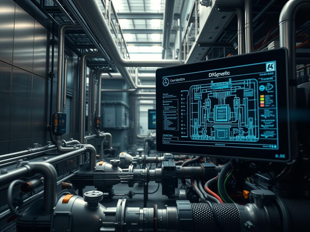
Industrial Waste Heat Pumps function as the primary thermodynamic bridge between discarded process energy and high demand thermal requirements. These systems are positioned at the intersection of energy and industrial water infrastructure; they serve as a critical mechanism for recovering low enthalpy heat and upgrading it to usable process temperatures. By successfully reintegrating thermal energy that would otherwise be rejected to the atmosphere or a cooling body, Industrial Waste Heat Pumps significantly reduce the primary fuel payload of a facility. This prevents energy waste while simultaneously lowering the operational overhead associated with heat generation and rejection. Within a modern industrial stack, these pumps are managed via distributed control systems that monitor fluid flow, pressure gradients, and refrigerant state changes. Scaling this infrastructure requires a systemic approach to managing thermal-inertia and reducing the latency of the heat exchange cycle. This manual provides the architectural framework for implementing, configuring, and scaling these hardware assets within a resilient industrial environment.
TECHNICAL SPECIFICATIONS
| Requirements | Default Port/Operating Range | Protocol/Standard | Impact Level (1-10) | Recommended Resources |
|—|—|—|—|—|
| Edge Controller | Port 502 (Modbus TCP) | IEC 61131-3 | 8 | 4-Core ARM / 8GB RAM |
| Terminal Evaporator | 25 to 75 Celsius | ASME BPVC Section VIII | 9 | Grade 316L Stainless |
| Telemetry Stream | Port 8883 (MQTTS) | OASIS MQTT v5.0 | 7 | CAT6A or Fiber Optic |
| Power Infrastructure | 480V / 60Hz 3-Phase | IEEE 1584 / NEC 430 | 10 | 250A Dedicated Feed |
| Flow Management | 100 to 1000 GPM | ANSI/HI 14.1 | 8 | Variable Freq Drive |
| Thermodynamic Medium | Low GWP Refrigerants | ASHRAE Standard 34 | 9 | R-1233zd or R-717 |
THE CONFIGURATION PROTOCOL
Environment Prerequisites:
Successful deployment requires an environment compliant with NEC-Article-430 for motor controllers and IEEE-802.3 for network redundancy. Hardware dependencies include a Programmable-Logic-Controller with an available RS-485 or Ethernet-IP interface and a dedicated Variable-Frequency-Drive for the compressor motor. Software requirements include Python-3.10+ for custom analytics scripts and OpenSSL-3.0 for securing telemetry payloads. Users must possess administrative privileges on the SCADA-Terminal and root access to the Edge-Gateway.
Section A: Implementation Logic:
The engineering design of Industrial Waste Heat Pumps centers on maximizing the Coefficient of Performance (COP) by minimizing the temperature lift between the heat source and the heat sink. The underlying logic follows a vapor compression cycle where the Evaporator absorbs waste heat to boil a refrigerant, which is then mechanically compressed to increase its thermal density. We prioritize a high-concurrency control strategy where the PID-Controller adjusts motor speed in real time based on the load profile of the waste stream. By accounting for thermal-inertia, the system prevents rapid cycling of the Compressor-Motor, which protects the physical hardware while ensuring stable throughput. Encapsulation of sensor data within standardized industrial protocols ensures that the thermal telemetry can be parsed by any upstream monitoring service without significant packet-loss or signal-attenuation.
Step-By-Step Execution
1. Structural Mounting and Isolation
Secure the Industrial-Waste-Heat-Pump chassis to the facility floor using Vibration-Isolators and heavy-duty Anchoring-Bolts.
System Note: High-mass isolation is required to dampen the mechanical resonance produced by the Screw-Compressor; this prevents harmonic vibration from causing physical micro-fractures in the Refrigerant-Piping.
2. Primary Heat Exchanger Integration
Connect the waste heat source piping to the Evaporator-Inlet using Flange-Gaskets rated for the specific chemical composition of the fluid.
System Note: Proper manifold alignment reduces the hydraulic overhead on the Circulation-Pumps, ensuring that fluid velocity remains within the laminar flow regime to prevent cavitation.
3. Electrical and VFD Provisioning
Terminate the 3-phase power supply into the Variable-Frequency-Drive and link it to the Compressor-Motor-Terminals.
System Note: The VFD acts as a power-conditioning layer that mitigates inrush current; it allows the system to scale its energy consumption linearly with the thermal payload.
4. Logic Controller Network Initialization
Initialize the network interface on the PLC and assign a static IP address using the command ip-addr-add-192.168.1.50/24-dev-eth0.
System Note: Establishing a dedicated subnet for the Industrial-Waste-Heat-Pump prevents bridge-looping and mitigates the risk of broadcast storms affecting the control-plane.
5. Sensor Calibration and Handshaking
Verify the resistance values of the PT100-RTD sensors using a Fluke-Multimeter before connecting them to the Analog-Input-Module.
System Note: Accurate calibration at the physical layer ensures that the SCADA-System receives a precise thermal-gradient reading, which is essential for the idempotent execution of safety-cutoff logic.
6. PID Loop Configuration
Modify the control parameters in the /etc/hvac/pid_settings.conf file, specifically tuning the Proportional-Gain and Integral-Time variables.
System Note: Tuning these variables reduces the latency between a detected change in heat load and the corresponding adjustment in compressor speed; this maintains the target output temperature.
7. Telemetry Payload Dispatch
Enable the MQTT-Broker service on the Edge-Gateway using systemctl-enable-mosquitto.
System Note: This initiates the outbound data stream; it packages thermal efficiency metrics into a JSON-formatted payload for ingestion by the facility’s energy management software.
Section B: Dependency Fault-Lines:
Installation failures often emerge from a mismatch between the refrigerant charge and the Expansion-Valve orifice size. If the refrigerant is undercharged, the Evaporator will experience “starvation,” leading to low suction pressure and potential high-temperature failures at the Compressor-Discharge. Conversely, overcharging can lead to liquid slugging where incompressible fluid enters the Compressor, causing catastrophic mechanical failure. On the digital side, library conflicts between Modbus-Python wrappers and local Kernel-Drivers for serial ports can lead to intermittent data loss. Ensure that all serial interfaces are mapped correctly to /dev/ttyUSB0 or /dev/ttyS0 with the correct baud rate (typically 9600 or 19200) to prevent signal-attenuation issues.
THE TROUBLESHOOTING MATRIX
Section C: Logs & Debugging:
When the system triggers a hardware interrupt, the first point of analysis should be the Alarms-Log stored at /var/log/hvac/alarms.log. Specific error strings like “E-PRES-004” indicate a high-pressure cutout usually caused by a failure in the Condenser-Fan or a blockage in the coolant line. Use the command tail-f-/var/log/hvac/alarms.log to monitor real-time fault codes during system commissioning. If the Modbus link fails, use tcpdump-i-eth0-port-502 to inspect packet traffic. Look for “TCP Retransmission” or “Empty Payload” flags; these indicate substantial packet-loss or incorrect slave-ID mapping. If the physical sensor readout deviates from the logic-controller display, verify the Signal-Conditioner at the Terminal-Block. A discrepancy here points to electromagnetic interference (EMI) affecting the low-voltage signal wires.
OPTIMIZATION & HARDENING
– Performance Tuning: To maximize throughput, implement a staging logic where multiple Industrial Waste Heat Pumps are sequenced based on their runtime hours. Adjust the Dead-Band settings in the control software to prevent two units from fighting over the same thermal-inertia window. This ensures that the system maintains high efficiency while minimizing cumulative mechanical wear.
– Security Hardening: Implement strict iptables rules to restrict access to Port-502 and Port-8883. Use the command iptables-A-INPUT-p-tcp-s-10.0.0.5–dport-502-j-ACCEPT to allow only the authorized SCADA server to communicate with the pumps. Disable all unused services such as SSH or HTTP on the field controllers to reduce the attack surface.
– Scaling Logic: When expanding the infrastructure to include additional heat pump clusters, utilize a load-balancer (physical or virtual) to distribute the thermal-payload. This allows the facility to scale horizontally. As the system grows, transition from a single-broker MQTT architecture to a clustered Broker-Mesh to handle increased concurrency and telemetry volume without increasing network latency.
THE ADMIN DESK
How do I reset the High-Pressure-Cutout?
Locate the HP-Reset-Button on the side of the Control-Cabinet. Ensure the Condenser is clear of debris. Once cleared, depress the physical button and clear the software latch in the PLC-Interface.
Why is the COP lower than specified?
Check for fouling in the Heat-Exchanger-Plates. A thin layer of mineral buildup creates significant thermal-resistance. Use a Chemical-Cleaning-Loop to restore thermal-conductivity and check the Refrigerant-Charge levels for deviations.
Can I monitor the system via a remote VPN?
Yes. Route the SCADA traffic through a WireGuard or OpenVPN tunnel. Ensure that the Firewall on the Edge-Gateway is configured to allow encrypted traffic while dropping all unauthenticated packets on the public interface.
What causes “E-COMM-TIMEOUT” errors?
These are typically caused by grounding loops or improper termination of the RS-485 bus. Ensure a 120-Ohm-Resistor is placed at both ends of the communication line to prevent signal reflection and attenuation.
How often should the compressor oil be analyzed?
Perform a Spectrographic-Oil-Analysis every 4,000 operational hours. This proactively identifies internal wear on the Main-Bearings before a catastrophic failure occurs: specifically looking for copper or iron particulates in the lubricant.