
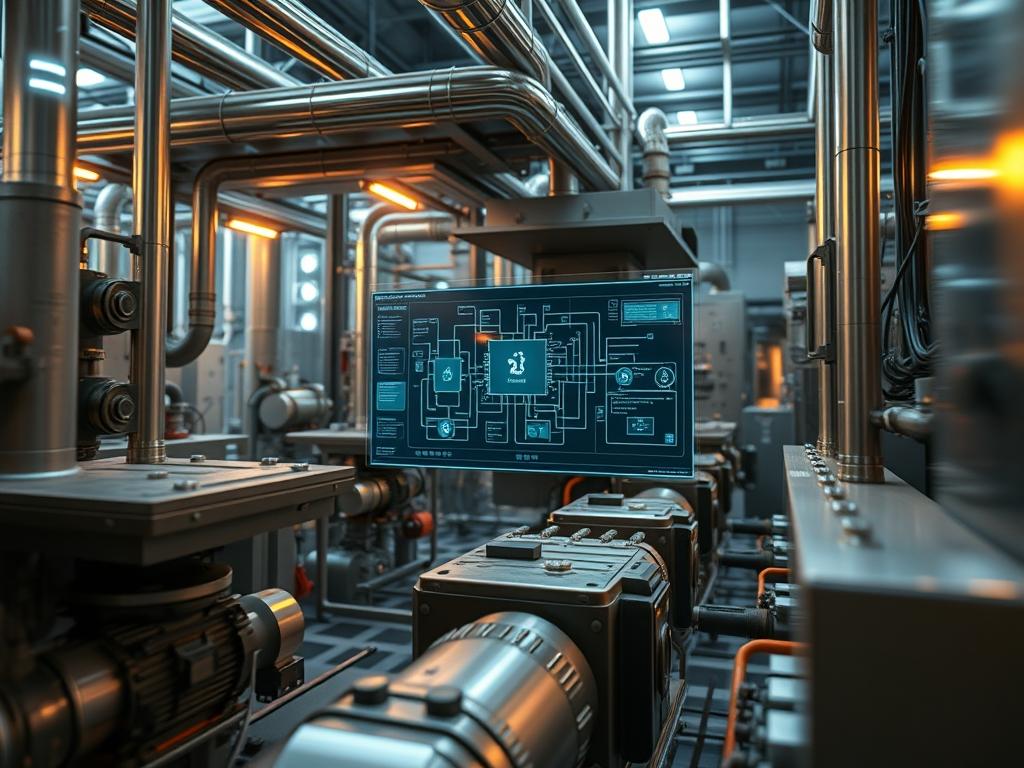
Biomass Direct Combustion Logic (BDCL) represents the operational core of industrial energy systems designed to convert organic matter into usable thermal or electrical energy. Within the broader technical stack; encompassing energy production, water cycle management, and cloud-integrated SCADA (Supervisory Control and Data Acquisition) networks; BDCL serves as the deterministic layer that governs the physical oxidation process. The management of flame geometry is the critical success factor in this domain. Improper flame propagation leads to localized slagging, excessive NOx emissions, and reduced thermal throughput. The problem-solution context focuses on the precise manipulation of primary, secondary, and tertiary air vectors to maintain an optimal stoichiometry. By applying rigorous logic to the feedback loops of oxygen sensors, optical pyrometers, and fuel-feed actuators, architects can ensure that the combustion process remains within a narrow corridor of efficiency. This manual provides the technical framework necessary to implement, monitor, and troubleshoot these complex logic gates to prevent hardware degradation and optimize fuel consumption across large-scale infrastructure deployments.
TECHNICAL SPECIFICATIONS
| Requirement | Default Port/Operating Range | Protocol/Standard | Impact Level (1-10) | Recommended Resources |
| :— | :— | :— | :— | :— |
| Logic Controller (PLC) | 24V DC / 1.2GHz | IEC 61131-3 | 10 | 4GB RAM / Quad-core |
| O2 Trim Sensor | 4-20mA Signal Loop | HART / Modbus TCP | 9 | Zirconia Cell Grade A |
| Airflow Actuators | 0-90 Degree Rotation | Profibus DP | 7 | High-torque Servo |
| Telemetry Uplink | Port 1883 or 8883 | MQTT / TLS 1.3 | 6 | Cat6a / Fiber Optic |
| Refractory Material | 1,200C – 1,600C | ASTM C155 | 8 | 60%+ Al2O3 Content |
THE CONFIGURATION PROTOCOL
Environment Prerequisites:
Successful deployment of Biomass Direct Combustion Logic requires adherence to strict industrial standards and hardware baselines. The system must comply with NEC Article 700 for emergency power and IEEE 802.3 for robust network physical layers. Users must possess Level 3 Administrative Access (Root/Sudo equivalent on industrial controllers) to modify PID (Proportional-Integral-Derivative) constants within the Runtime Engine. All sensor arrays must be calibrated against a known standard using a fluke-multimeter or equivalent process calibrator. Fuel moisture content must remain below 20% to avoid logic-driven oscillations in the thermal-inertia compensation algorithms.
Section A: Implementation Logic:
The engineering design of BDCL relies on the principle of idempotent control signals; every command issued by the controller must result in a predictable, repeatable state regardless of the initial conditions. The core logic utilizes a feed-forward model to anticipate fuel quality shifts. Because biomass has high moisture variability, the controller must calculate the energy density of the fuel-payload in real time by measuring the temperature delta across the primary heat exchanger. This information is then used to adjust the flame geometry. If the flame is too long, it risks impingement on the rear tube bank, causing thermal stress. If it is too short, carbon carryover increases, reducing overall throughput. The logic gates encapsulate these variables, reducing the overhead on the central processor by handling fast-loop calculations locally at the I/O-module level.
Step-By-Step Execution
1. Initialize the Core Logic Controller
Access the controller interface via the 192.168.1.10 management port or the dedicated serial console. Ensure the firmware-version-4.5.2 or higher is active. Load the combustion_logic_v1.bin file into the non-volatile memory.
System Note: This action initializes the kernel-level interrupts for the combustion cycle; ensuring that safety-critical routines have priority over secondary telemetry tasks.
2. Configure Primary Airflow Ratios
Navigate to /config/air/primary_ratio.cfg and set the base value to 0.40 of total air volume. Use the set_value –primary 40 command to lock the damper position at the minimum ignition threshold.
System Note: Setting this variable establishes the foundation for the flame root; a stable primary ratio prevents the flame from detaching from the burner head during high-velocity transitions.
3. Calibrate Secondary Air Injection Vectors
Deploy a pitot-tube into the secondary air ducts to verify physical velocity against the digital readout in the SCADA-interface. Adjust the proportional-gain in the secondary air PID loop to 1.2.
System Note: This step controls the flame width and swirl. By increasing the secondary air velocity, the logic increases the centrifugal force on the fuel particles; which improves mixing and reduces the latency of the combustion reaction.
4. Establish Oxygen Trim Setpoints
Open the modbus-register-map.xlsx to identify the address for the stack O2 sensor (Address 40003). Set the target O2 level to 3.5% for dry fuel and 5.0% for high-moisture fuel.
System Note: The O2 trim acts as the final feedback loop; it fine-tunes the geometry by thinning or thickening the fuel-air mixture to ensure complete oxidation without excessive cooling from parasitic air.
5. Benchmark Thermal Inertia Constants
Run the system-diag –thermal-ramp command to measure the time delay between fuel feed increase and discharge temperature rise. Input this value into the inertia_offset variable in the controller.
System Note: This logic compensates for the physical time it takes for biomass to ignite. Proper calibration prevents a “runaway” condition where the logic adds too much fuel while waiting for a temperature response.
Section B: Dependency Fault-Lines:
The most common bottleneck in Biomass Direct Combustion Logic is signal-attenuation within the sensor feedback loops. High-temperature environments generate significant EMI (Electromagnetic Interference); which can corrupt the 4-20mA signals from the pyrometers. If the logic receives a “noisy” signal, the PID loop will vibrate the air dampers, leading to mechanical fatigue. Another critical failure point is the fuel delivery consistency. If the auger speed varies by more than 5%, the concurrency of the air-fuel mixing logic is broken; leading to “slugs” of unburnt fuel and potential packet-loss in the data stream if the controller attempts to over-correct.
THE TROUBLESHOOTING MATRIX
Section C: Logs & Debugging:
When the system detects an anomaly in the flame geometry; such as a “lift-off” condition or a “lazy flame” signature; it generates a specific error code in the system log found at /var/log/combustion/events.log.
- Error E042 (Flame Scanned Signal Low): This indicates that the optical sensor cannot detect the UV/IR signature of the flame. Check the quartz-viewing-lens for soot buildup. Use chmod 755 on the log directory if access is denied during debugging.
- Error E109 (High Differential Pressure): This usually points to a physical blockage in the tertiary air ports. Verify the pressure transducer at PT-202 using a manometer.
- Packet-Loss at Gateway: If telemetry is missing, check the MQTT-broker status. A high overhead on the network can cause a delay in the O2 trim signal, causing the controller to default to a “Safe Mode” rich-burn state.
Visual inspection of the flame through the inspection-port should show a bright yellow, swirling vortex. A dark red or smoky flame suggests oxygen starvation; while a blinding white flame indicates excessive air and potential refractory damage.
OPTIMIZATION & HARDENING
Performance Tuning:
To maximize throughput, implement a “fuzz-logic” overlay on the standard PID controls. This allows the system to deviate slightly from the setpoints to account for non-linear fuel characteristics. Increasing the concurrency of the sensor polling rate from 100ms to 50ms will reduce the latency in air adjustments; though this requires a high-performance logic-controller with sufficient CPU-overhead.
Security Hardening:
Industrial networks are frequent targets for lateral movement. Isolate the combustion logic subnet using a Layer-3-firewall with strict ingress/egress rules. Only allow traffic on Port 502 (Modbus) from verified Engineering Workstation IPs. Ensure all SSH access to the controller uses public-key authentication rather than simple passwords. Physical fail-safes; such as mechanical pressure-relief-valves and hard-wired-estops; must remain independent of the software logic to ensure safety during a total kernel panic.
Scaling Logic:
When expanding the system to include multiple burners (Multi-Burner Array), the logic must shift to a “Master-Slave” architecture. The Master-PLC calculates the total load demand and distributes the payload across individual Slave-Controllers. This methodology ensures that each burner maintains its own optimal flame geometry while contributing to the collective thermal demand.
THE ADMIN DESK
How do I reset the O2 trim logic after a sensor failure?
Access the calibration-menu, select sensor-reset, and perform a “Pure Air” span check. Ensure the signal-loop is closed and the controller reads 20.9% O2 before re-enabling the automatic trim function to prevent logic crashes.
What is the fastest way to stabilize a flickering flame?
Increase the secondary-air-damper position by 5% increments while monitoring the flame-scanner intensity. This usually increases the turbulence and anchors the flame root more effectively to the burner head.
Why does the system log show “High Thermal Overhead”?
This occurs when the discharge-temperature exceeds the logic-threshold for more than 60 seconds. Check the water-pump-flow and ensure the heat-exchanger is not fouled, as this prevents heat transfer and causes combustion heat to back up.
How can I reduce NOx emissions without losing efficiency?
Decrease the primary-air and move the volume to the tertiary-air stage. This “staged combustion” logic lowers the peak flame temperature, which is the primary driver of thermal NOx formation, while maintaining high total burnout rates.