
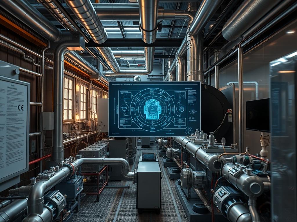
Hydrogen Ready Boiler Tech represents a critical pivot in the global energy stack; it functions as a bridge between legacy methane based thermal systems and future zero emission hydrogen infrastructures. Within the context of decentralized heating and industrial process steam, these systems must solve the fundamental problem of hydrogen embrittlement while maintaining high thermal-inertia for industrial loads. While traditional natural gas boilers utilize carbon steel components, Hydrogen Ready Boiler Tech demands a significant upgrade in material science to handle the unique chemical footprint of the hydrogen molecule. This transition involves modifying the burner geometry, enhancing flame detection sensors, and replacing standard valve seals with elastomers that prevent the leakage of small diameter hydrogen molecules. The implementation of this technology ensures that infrastructure built today remains idempotent against future fuel shifts; the hardware is capable of running on natural gas now and switching to 100 percent hydrogen with minimal onsite component replacement. This design strategy mitigates the risk of stranded assets during the decarbonization of the heating grid.
Technical Specifications
| Requirement | Default Port/Operating Range | Protocol/Standard | Impact Level (1-10) | Recommended Resources |
| :— | :— | :— | :— | :— |
| Combustion Temp | 1200C to 1500C | ASME B31.12 | 9 | AISI 316L Stainless Steel |
| Gas Supply Pressure | 20 mbar to 300 mbar | ISO 14687 | 7 | High-Tensile Alloy Tubing |
| Control Interface | Modbus TCP / 502 | IEEE 802.3 | 6 | 1GHz CPU / 512MB RAM |
| Flame Velocity | 2.6 m/s to 3.2 m/s | NFPA 54 | 10 | Nickel-Chrome Burner Mesh |
| Seal Integrity | < 1.0 x 10^-5 mbar.l/s | EN 15502-1 | 8 | Viton or PTFE Gaskets |
| Stoichiometric Ratio | 2.38:1 (Air:H2 Vol) | ISO/TC 197 | 9 | Precision Logic Controller |
The Configuration Protocol
Environment Prerequisites:
Installation of Hydrogen Ready Boiler Tech requires strict adherence to ASME B31.12 for hydrogen piping and NFPA 2 for hydrogen safety. The underlying control logic must reside on a system running a Real-Time Operating System (RTOS) capable of managing millisecond-level interrupts. User permissions for firmware updates must be restricted to the admin or root level via secure SSH or hardware-keyed access. All physical components must be degreened and cleaned for oxygen/hydrogen service to prevent lipid-based combustion within the delivery lines.
Section A: Implementation Logic:
The engineering design centers on the high flame speed and low ignition energy of hydrogen. Hydrogen possesses a laminar burning velocity nearly ten times that of methane; this necessitates a physical reconfiguration of the burner head to prevent flashback, where the flame travels backward into the premix chamber. The implementation logic utilizes a high-headroom approach for air supply, ensuring that the throughput of air is sufficient to manage the increased thermal load on the heat exchanger. Furthermore, the encapsulation of the combustion chamber must account for the specific chemical byproduct of H2 combustion: water vapor. High condensation rates require a drainage system capable of handling acidic condensate while maintaining the pressure seal.
Step-By-Step Execution
1. Burner Head Assembly and Material Verification
Inspect the burner-assembly for the presence of micro-porosity. Install the AISI-316L-burner-matrix into the primary combustion manifold.
System Note: This action sets the physical boundary for flame propagation. By using high-grade stainless steel, the system reduces the risk of hydrogen-induced cracking (HIC) at the atomic level, where hydrogen atoms would otherwise diffuse into the metal lattice and cause structural failure.
2. Integration of the Ultraviolet Flame Sensor
Mount the UV-sensor-probe at a 45-degree angle to the pilot ignition point. Connect the sensor lead to the analog-input-port-01 of the Boiler Management System (BMS).
System Note: Traditional ionization probes fail in hydrogen environments because the flame lacks the carbon particles required for a reliable rectification signal. The UV sensor provides a zero-latency feedback loop to the kernel, allowing for immediate fuel-cutoff if the flame signal drops below the 4mA threshold.
3. Logic Controller Firmware Deployment
Upload the updated stoichiometry maps to the plc-controller-memory. Use scp /path/to/h2_config.bin root@192.168.1.50:/etc/boiler/config. Restart the control service using systemctl restart boiler-mgmt.service.
System Note: This update modifies the PID loops and fuel-to-air ratios. The service restart refreshes the memory registers, ensuring that the payload of fuel delivered per stroke of the pulse-width modulation (PWM) valve corresponds specifically to the energy density of hydrogen versus methane.
4. Pressure Vessel Leak Simulation and Vacuum Hold
Seal the gas train and apply a 10 bar nitrogen purge followed by a vacuum draw. Monitor the fluke-675-pressure-transducer for any signal-attenuation or pressure decay over a 1-hour window.
System Note: This process verifies the integrity of all flanged connections. Hydrogen’s small molecular size causes significant packet-loss of physical gas if even microscopic gaps exist; this step ensures the physical layer of the infrastructure is hardened against atmospheric contamination.
5. Final Calibration of the Variable Speed Drive
Adjust the VSD-fan-controller to provide a minimum pre-purge of five times the combustion chamber volume. Execute the command vsd-tool –set-min-rpm 2800.
System Note: This ensures that any residual hydrogen from a failed ignition is evacuated before a secondary ignition attempt occurs. It prevents high-pressure transients within the chamber that could exceed the mechanical yield strength of the casing.
Section B: Dependency Fault-Lines:
The primary failure point in Hydrogen Ready Boiler Tech is the “Flashback” scenario. This occurs when the gas velocity through the burner ports drops below the flame speed. Another significant bottleneck is the “Thermal-Inertia Lag” during cold starts; hydrogen produces a very high-intensity flame that can cause localized hot spots on a cold heat exchanger, leading to thermal shock. Library conflicts in the BMS software can also occur if the Modbus registers for the O2 trim sensors are not properly mapped to the new hydrogen-specific sensor ranges.
THE TROUBLESHOOTING MATRIX
Section C: Logs & Debugging:
When diagnosing system instability, the first point of reference is the high-level system log located at /var/log/boiler/error.log. Search for the error string ERR_FLAME_STABILITY_0x44; this typically indicates a high-frequency flicker in the burner, often caused by improper air-fuel mixing. If the physical sensors report a 0.00V reading on the gas valve feedback loop, check the modbus-tcp status for packet-loss across the local network segment.
Physical fault codes are visible on the HMI (Human Machine Interface). Fault code F.28 signifies an ignition failure after three attempts. In a hydrogen context, this usually points to poor gas purity or an incorrect spark gap. Verify the spark electrode gap using a feeler-gauge; it must be set to precisely 3.5mm to ensure consistent arc generation in the less-dense hydrogen mix. If the log displays OVERHEAT_TRIP, investigate the thermal-inertia of the secondary loop; a failure in the circulating pump often leads to a rapid spike in the primary exchanger temperature due to the high energy throughput of hydrogen.
OPTIMIZATION & HARDENING
Performance Tuning:
To maximize thermal efficiency, implement an “Oxygen Trim” logic that utilizes a zirconia-sensor to monitor the flue gas. Adjust the concurrency of the fan and gas valve response times to minimize the excess air ratio. Reducing excess air from 20 percent to 5 percent can improve overall system throughput and reduce the energy overhead required to heat unnecessary ambient air. Ensure the PID loop tuning is aggressive enough to handle the rapid temperature spikes characteristic of hydrogen combustion.
Security Hardening:
Physical fail-safes must be hard-wired and bypass the software layer. An over-temperature-limit-switch must be installed in series with the main gas solenoid valve. On the digital side, harden the networking stack by disabling all unused ports on the BMS. Apply iptables rules to allow only known IP addresses from the SCADA (Supervisory Control and Data Acquisition) server to communicate with the boiler’s Modbus interface. This prevents unauthorized modification of the combustion parameters which could lead to intentional equipment damage.
Scaling Logic:
As demand increases, multiple hydrogen-ready units should be configured in a “Master-Slave” cascade. This allows for high concurrency in load management. The orchestration software should rotate the “Lead” boiler based on total run-time hours to ensure even wear across the fleet. Scaling should also involve the installation of a central hydrogen manifold with a shuttle-valve system to maintain pressure stability during peak demand periods, preventing signal-attenuation in the pressure sensors across the distributed system.
THE ADMIN DESK
FAQ 1: Why does the system report a flame failure despite high heat?
Hydrogen flames are invisible to standard infrared sensors. Ensure the UV-sensor-probe is clean and properly aligned. Check the BMS logs for signal-attenuation in the 200-280nm ultraviolet spectrum.
FAQ 2: Can I use standard copper piping for the hydrogen supply?
No; copper can suffer from hydrogen embrittlement over time. Use AISI-316L-stainless-steel or approved high-pressure polymers to maintain the integrity of the delivery path and prevent catastrophic leakage.
FAQ 3: How does the system manage the increased condensate volume?
Hydrogen combustion produces roughly three times more water vapor than methane. Ensure the condensate-trap and drainage pipes are upsized to prevent water backup into the combustion chamber, which causes rapid cooling and shutdowns.
FAQ 4: Is a firmware roll-back required when switching back to methane?
Yes; the stoichiometric requirements differ significantly. Use an idempotent configuration script to toggle between fuel profiles. This ensures the correct air-to-fuel ratio and prevents an oxygen-rich environment that could damage the burner components.