
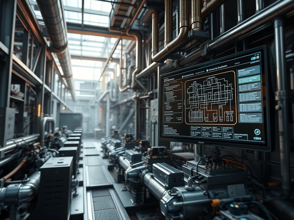
Biomass gasification principles revolve around the thermochemical breakdown of organic matter under sub-stoichiometric oxygen levels to synthesize a combustible gas mixture known as syngas. This process sits at the foundation of modern sustainable energy infrastructure; it offers a high-efficiency bridge between raw carbonaceous feedstock and high-grade thermal or electrical output. In the current infrastructure stack, gasification functions as a high-concurrency chemical reactor where feedstock payload is converted into energy with minimal environmental overhead. The primary engineering challenge addresses the optimization of thermal conversion efficiency, which is often inhibited by high thermal-inertia and latency in heat transfer across the reactor bed. By applying rigorous control logic and precise material handling, architects can mitigate signal-attenuation in sensor arrays and ensure that the chemical throughput remains consistent under fluctuating load profiles. This manual outlines the architectural requirements for achieving peak thermal performance while maintaining system integrity through advanced monitoring and hardening protocols within a distributed energy network.
TECHNICAL SPECIFICATIONS
| Requirement | Operating Range | Standard | Impact Level | Recommended Resources |
| :— | :— | :— | :— | :— |
| Feedstock Moisture Content | 10% to 20% | ISO 17225-1 | 9 | Pre-processing dryer |
| Reactor Temperature (Bed) | 750C to 1150C | ASME PTC 46 | 10 | Inconel 601 Alloy |
| Equivalence Ratio (ER) | 0.20 to 0.40 | ASTM E870-82 | 8 | Mass Flow Controller |
| Syngas Calorific Value | 4.5 to 6.0 MJ/Nm3 | ISO 6976 | 7 | PLC-controlled scrubbing |
| Control Logic Latency | < 50ms | IEEE 1547 | 6 | Siemens S7-1500 / 32GB RAM |
| Particle Size Distribution | 20mm to 50mm | DIN EN 15149 | 8 | Industrial Wood Chipper |
| Refractory Thermal-Inertia | High-Density Alumina | ASTM C155 | 9 | 150mm Thickness |
THE CONFIGURATION PROTOCOL
Environment Prerequisites:
Before initiating the deployment of the gasification control stack, the systems architect must verify the following dependencies:
1. Compliance with NEC Article 500 for hazardous locations; specifically Class I, Division 2 environments where flammable gases are present.
2. Installation of a real-time operating system (RTOS) or a hardened Linux kernel (e.g., Ubuntu Server 22.04 LTS with the RT-PREEMPT patch) to handle high-concurrency sensor data.
3. Physical infrastructure must include a multi-stage gas cleaning unit with a cooling capacity capable of reducing gas temperature to < 40C to prevent downstream engine fouling.
4. User permissions: Root-level access to the Modbus/TCP gateway and administrative rights on the human-machine interface (HMI).
Section A: Implementation Logic:
The engineering design relies on the principle of partial oxidation to provide the heat required for endothermic reduction. Unlike combustion, which aims for a high air-fuel ratio, gasification necessitates a carefully tuned sub-stoichiometric oxygen supply. The efficiency of the system is a function of the Cold Gas Efficiency (CGE), defined as the ratio of the energy content of the syngas to the energy content of the input biomass. To minimize the thermal-inertia of the reactor, the internal shell must use high-grade refractory encapsulation to prevent radiant heat loss. The logic controller must maintain an idempotent state for the air-intake valves; this ensures that a command for a 10 percent increase in oxygen results in the same physical state regardless of previous commands. This reduces the overhead of the feedback loop and prevents thermal runaway caused by oscillating control signals.
Step-By-Step Execution
1. Initialize Feedstock Metering
Execute the calibration of the variable frequency drive (VFD) controlling the screw conveyor.
System Note: This sets the baseline throughput for the carbon payload. Use the command vfd-tool –set-freq 45Hz –node-id 0x01 to establish the initial mass flow rate. The controller must audit the torque to detect bridge formation in the hopper.
2. Configure Air Intake Logic
Access the PID-controller settings in the PLC software environment to define the air-to-fuel ratio.
System Note: Precise oxygen ingress is critical. Adjust the P-gain to 1.5 and I-gain to 0.8 to minimize latency in the thermal response. Use chmod 664 /etc/scada/air_ratio.conf to ensure the control service has the correct read/write permissions for the config file.
3. Establish Thermal Monitoring Matrix
Connect a series of K-type thermocouples to the thermocouple-module of the PLC.
System Note: Real-time monitoring of the oxidation, reduction, and pyrolysis zones is mandatory. The architecture uses four-wire compensation to mitigate signal-attenuation over long cable runs. Verify connectivity with a fluke-754 documenting process calibrator.
4. Deploy Syngas Extraction Blower
Start the induced draft fan via the systemctl start id-fan.service command.
System Note: This creates a negative pressure environment inside the reactor, ensuring that syngas flows through the filtration sequence without leakage. The blower speed should be mapped to the reactor pressure transducer to maintain a constant vacuum of -500 Pa.
5. Activate Gas Cleaning Subsystem
Initiate the water circulation pumps and the electrostatic precipitator.
System Note: The gas cleaning unit handles the removal of tars and particulates. High tar loads increase the viscosity of the scrubbing fluid, resulting in parasitic energy overhead for the pumps. Monitor the differential pressure across the filter using modbus-query -r 40012.
6. Calibrate Gas Composition Sensors
Run a zero-calibration routine on the infrared (IR) gas analyzer.
System Note: The analyzer measures concentrations of CO, H2, and CH4. Accurate readings are required to calculate the stoichiometric requirements for the downstream engine or boiler. Check the output stream for any evidence of packet-loss between the analyzer and the HMI.
7. Trigger Ignition Sequence
Engage the electric igniter and monitor the temperature ramp-up at the lower grate.
System Note: The ignition system must follow a strict safety interlocking logic. If the temperature fails to reach 400C within 300 seconds, the PLC must trigger an automated shutdown –now to prevent the accumulation of unreacted volatiles.
8. Optimize Reduction Zone Heat
Adjust the height of the grate or the speed of the ash discharge screw.
System Note: Proper ash management ensures that the reduction zone remains hot and porous. Insufficient ash removal increases the thermal-inertia of the bed, leading to cold spots and reduced conversion efficiency. Use ash-controller –status to check for clinkering.
Section B: Dependency Fault-Lines:
Systems frequently fail during the transition from the pyrolysis phase to the reduction phase. If the moisture content of the feedstock exceeds 20 percent, the latent heat of vaporization absorbs a significant portion of the energy payload, dropping the bed temperature below the tar-cracking threshold (approx. 800C). This leads to mechanical bottlenecks in the filters. Furthermore, signal-attenuation in the RS-485 communication lines between the reactor and the control room can lead to outdated sensor data being fed into the PID loop, causing significant latency in emergency response. Always ensure shielded twisted-pair cabling is used for all Modbus communications.
THE TROUBLESHOOTING MATRIX
Section C: Logs & Debugging:
When a thermal efficiency drop is observed, the architect must first inspect the logs located at /var/log/energy/gasifier_audit.log. Look for error code ERR_502_THERMAL_LAG, which indicates the reactor is not reaching the required setpoint despite maximum oxygen throughput.
Physical fault codes on the PLC front panel should be cross-referenced with the scada dashboard. If the dashboard shows a flatline in temperature while the PLC shows a fluctuation, the issue is likely packet-loss in the local network or a failure in the TCP/IP stack of the gateway. Use tcpdump -i eth0 port 502 to analyze traffic for malformed Modbus packets. If the oxygen levels are spiking without a corresponding temperature increase, inspect the reactor for “channeling,” where air bypasses the fuel bed through a physical void.
OPTIMIZATION & HARDENING
– Performance Tuning: To maximize throughput, the system should implement a fuzzy-logic controller that can anticipate changes in feedstock density. By adjusting the Equivalence Ratio in real-time based on the caloric output of the syngas, the system reduces the thermal-inertia of the reaction. Increasing the reactor insulation to ultra-high-density ceramic fiber will further reduce the energetic overhead.
– Security Hardening: The control network must be isolated from the corporate WAN. All PLC communication should reside on a separate VLAN with strict MAC-address filtering. Apply iptables rules to drop all traffic except for authorized HMI nodes. Ensure the physical cabinet is locked and equipped with tamper-detection sensors that trigger a safety-stop to the fuel input screw.
– Scaling Logic: When moving from a single 250kW unit to a 1MW cluster, manage the load via a distributed message broker (e.g., MQTT). Each gasifier operates as an independent node in a mesh network, allowing for maintenance on one unit without interrupting the energy throughput of the entire plant.
THE ADMIN DESK
1. How do I fix low syngas quality?
Check the feedstock moisture content and the Equivalence Ratio. If the ER is too high, you are essentially burning the syngas inside the reactor. Lower the air intake to shift the reaction toward reduction and increase the energetic payload.
2. What causes carbon buildup in the heat exchanger?
Frequent buildup indicates high tar levels caused by low bed temperatures. Verify that the reactor temperature is above 850C. High thermal-inertia in the heat exchanger tubes often results from insufficient soot-blowing cycles; increase the frequency of the pulse-jet cleaning.
3. How do I resolve PLC communication latency?
Examine the network for high signal-attenuation. Ensure all fieldbus terminators (120-ohm resistors) are present on the RS-485 loop. Check for electromagnetic interference from large VFDs and ensure that all signal cables are separated from power conductors by at least 150mm.
4. Why is the ash discharge screw jamming?
Jamming is usually caused by clinkers or slag formed by high ash-fusion temperatures. This happens when the oxidation zone exceeds 1200C. Calibrate your thermocouples to ensure the PLC is not reporting false lower temperatures that lead to excessive oxygen injection.
5. Is it safe to run a feedstock mix of 50/50?
Yes, but the logic controller must be tuned for the lower density. The concurrency of different chemical reactions for two feedstocks increases the complexity of the PID loop. Adjust the fuel feeding rate to compensate for differing caloric values.