
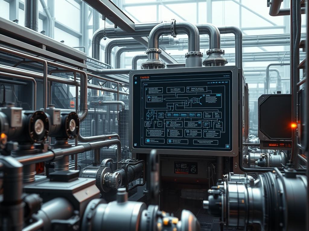
Waste Heat Steam Generators function as the primary energy recovery interface within high-output industrial ecosystems: capturing thermal energy from exhaust gas streams to produce high-pressure steam. These systems sit at a critical juncture between primary combustion turbines and secondary power or process cycles: effectively bridging the gap between waste extraction and utility generation. In a modern technical stack, the Waste Heat Steam Generator serves as a hardware-level recovery layer that reduces the thermal overhead of the entire facility. By mitigating the energy lost to the atmosphere, these units increase the total thermal efficiency of a combined cycle power plant from approximately 40 percent to over 60 percent. The problem addressed by this infrastructure is two-fold: environmental thermal pollution and industrial inefficiencies. The solution is an integrated heat exchanger network that manages complex thermodynamics while maintaining high throughput. This technical manual details the engineering requirements, configuration protocols, and maintenance logic necessary for deploying and auditing these assets in mission-critical environments.
TECHNICAL SPECIFICATIONS
| Requirements | Default Operating Range | Protocol/Standard | Impact Level (1-10) | Recommended Resources |
| :— | :— | :— | :— | :— |
| Inlet Gas Temp | 400C to 650C | ASME BPVC Section I | 10 | Material Grade: P91 Steel |
| Feedwater Pressure | 20 to 120 bar | ASME B31.1 | 9 | Multi-stage Centrifugal Pump |
| Control Logic | 10ms to 50ms Latency | IEC 61131-3 | 8 | Dual-Core PLC / 2GB RAM |
| Network Comms | 10/100 Mbps | Modbus TCP/IP | 6 | Cat6e Shielded / Fiber Optic |
| Steam Throughput | 50 to 500 t/h | ISO 9001:2015 | 9 | High-Capacity Stop-Check Valve |
| Drum Water Level | +/- 50mm Variance | ASME Section VII | 10 | Differential Pressure Transmitters |
THE CONFIGURATION PROTOCOL
Environment Prerequisites:
Successful deployment of a Waste Heat Steam Generator requires strict adherence to international engineering standards. All mechanical assemblies must comply with ASME Boiler and Pressure Vessel Code (BPVC) Sections I and VIII. Electrical and control systems must meet NEC Article 700 for emergency systems and IEEE 802.3 for robust networking of the Human Machine Interface (HMI). Personnel must possess Level III NDT Certification for weld inspections and State-specific Stationary Engineer Licenses for operational oversight. The system environment must be clear of combustible dust and maintain an ambient temperature range of -20C to 50C to prevent signal-attenuation in field instrumentation.
Section A: Implementation Logic:
The engineering design of a Waste Heat Steam Generator is predicated on the laws of thermodynamics: specifically the transfer of enthalpy from a high-temperature gas stream to a sub-cooled liquid. The theoretical “Why” involves the management of thermal-inertia. Because metal components expand at different rates, the configuration logic must prioritize gradual temperature ramps to prevent stress cracking in the Tube Bundle Headers. From a data perspective, the control system must remain idempotent: sending the same “Start” command multiple times must result in the same physical state without causing logic loops or secondary actuator cycles. We utilize encapsulation for sensor data, where raw voltage inputs from Type K Thermocouples are wrapped in digital protocols before reaching the Proportional-Integral-Derivative (PID) controller to minimize noise.
Step-By-Step Execution
1. Actuator and Sensor Calibration
The first phase involves verifying the accuracy of all field devices using a fluke-multimeter and a dry-block calibrator. Ensure that every PT100 RTD and Pressure Transmitter returns a 4-20mA signal that maps linearly to the physical variables.
System Note: This action establishes the baseline for the Input/Output (I/O) bus. Proper calibration ensures that the Kernel of the Programmable Logic Controller (PLC) receives accurate data, preventing premature safety trips during the startup sequence.
2. Cold Flow Path Verification
Manually cycle the Bypass Damper and the Main Steam Stop Valve to ensure full range of motion. Use the SCADA interface to force the Digital Output (DO) bits for each solenoid.
System Note: This command verifies the mechanical integrity of the final control elements. If the throughput of the exhaust gas is not correctly diverted via the Bypass Damper, the system may experience an uncontrolled thermal spike, leading to catastrophic failure of the Economizer tubes.
3. Feedwater System Initialization
Engage the Feedwater Pump (FWP) via the Variable Frequency Drive (VFD) at a low frequency of 15Hz to fill the Steam Drum. Monitor the Differential Pressure Transmitter to confirm the level transition from “Low-Low” to “Normal”.
System Note: Initiating the pump through a VFD reduces the electrical overhead and prevents water hammer. The PLC monitors the payload of water flowing into the drum to ensure the thermal-inertia of the dry tubes is not shocked by a sudden influx of cold water.
4. Logic Controller Boot and Interlock Check
Execute the Load Program command on the Logic Controller to initialize the safety interlocking sequence. Verify that the Emergency Shutdown (ESD) logic is “Set” and that no “Fault” bits are active in the Global Register.
System Note: The ESD logic resides at the highest priority level of the control task. Setting this ensures that if packet-loss occurs on the communication bus, the system defaults to a “Fail-Safe” state: closing fuel lines and opening vent valves.
5. Hot Start and Thermal Transition
Gradually open the Inlet Isolation Damper while monitoring the Superheater outlet temperature. The rate of rise should not exceed 5 degrees Celsius per minute to manage the expansion of the Chrome-Moly (P91) piping.
System Note: This step transitions the generator from a static state to a dynamic energy recovery state. The PID loops now take over concurrency management: balancing pump speed, valve position, and steam flow to maintain drum stability.
Section B: Dependency Fault-Lines:
Installation and execution failures typically originate at the intersection of mechanical hardware and digital signals. A common bottleneck is the latency between the Steam Drum Level Sensor and the Feedwater Control Valve. If the network experiences packet-loss exceeding 5 percent, the PID loop will oscillate, causing the water level to swing violently. Furthermore, mechanical dependencies such as the Chemical Dosing System are vital; a failure in the Phosphate Pump leads to rapid scale formation on the Evaporator tubes. This scaling increases the thermal resistance, requiring higher gas temperatures for the same steam throughput, which eventually leads to tube rupture from overheating.
THE TROUBLESHOOTING MATRIX
Section C: Logs & Debugging:
When a system fault occurs, the primary source of truth is the Event Historian located at /var/log/scada/whsg_main.log. Operators should look for specific error strings that indicate physical or logical failures.
– Error ERR_042_LEVEL_TRIP: Indicates a measurement mismatch between the three redundant Level Transmitters. Check the impulse lines for blockages or leakage.
– Error ERR_880_SIGNAL_LOST: Indicates high signal-attenuation on the RS-485 loop. Verify the end-of-line resistors and check for electromagnetic interference (EMI) from nearby high-voltage motors.
– Physical Cue: Blue Smoke: If the exhaust stack exhibits blue smoke, it indicates upstream turbine oil leakage being vaporized in the WHSG inlet; immediately engage the Bypass Damper.
– Log Entry: PID_SATURATION: The controller has reached its output limit. This is often caused by a mechanical valve being stuck in the closed position or a total loss of instrument air.
OPTIMIZATION & HARDENING
– Performance Tuning: To maximize thermal efficiency, implement an Oxygen Trim Standard. By monitoring the oxygen levels in the exhaust gas, the Logic Controller can modulate the soot-blower frequency to keep the Heat Transfer Coefficient at its peak. Minimizing the overhead of the blowing steam increases the net throughput of the system.
– Security Hardening: The SCADA network must be isolated from the corporate Local Area Network (LAN). Implement Layer 3 Firewall Rules that only allow traffic on Port 502 (Modbus) from authorized IP Addresses. Disable all unused services on the Logic Controller such as HTTP or FTP to prevent unauthorized firmware injections.
– Scaling Logic: For facilities expanding their thermal capacity, WHSG units should be deployed in a “Modular Train” configuration. Each unit remains autonomous with its own PLC, but all units report to a centralized Distributed Control System (DCS). This ensures that a failure in one unit does not impact the concurrency of the remaining recovery trains.
THE ADMIN DESK
FAQ 1: Why is my steam quality decreasing despite high gas temperatures?
This is typically due to “carryover” caused by high drum water levels or excessive chemical concentration. Check your Blowdown Valve operation and ensure the Demister Pads are not fouled.
FAQ 2: How often should I calibrate the safety relief valves?
Per ASME Section I, safety valves must be tested annually. Ensure the “Pop” pressure is within 1 percent of the stamped set pressure to maintain the integrity of the pressure vessel.
FAQ 3: Can I operate the WHSG without water for short durations?
Never. Operating a “dry” boiler with hot exhaust gases will cause immediate and permanent damage to the tubes. Always ensure the Bypass Damper is fully open before losing feedwater throughput.
FAQ 4: What causes the high vibration in the feedwater piping?
This is often a result of cavitation in the Feedwater Pump or a failed Check Valve. Verify that the Net Positive Suction Head (NPSH) meets the pump manufacturer specifications to prevent internal damage.