
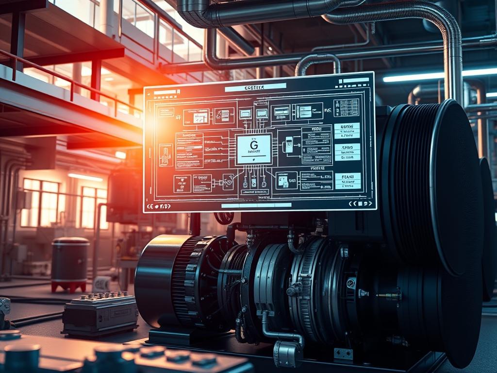
Brushless DC Compressor Logic (BDCL) represents a fundamental shift in fluid dynamics and thermal management within modern infrastructure stacks. Traditionally, compressor systems relied on induction motors that operated at fixed speeds; these legacy systems suffered from high inrush current and significant mechanical wear. By implementing BDCL, architects move the control layer from mechanical switches to a digital signal processor (DSP) or a dedicated microcontroller. This transition allows for variable speed control by modulating the frequency and voltage delivered to the motor windings. In the context of large-scale data centers or industrial cooling, the logic acts as a middleware between the raw environmental sensors and the physical hardware. It optimizes the power factor and eliminates the massive energy spikes associated with “hard starts.” The primary goal of this logic is the mitigation of thermal-inertia; it maintains a steady state rather than oscillating between high and low temperature extremes. This precision reduces the overall energy payload of the facility while increasing the longevity of the mechanical assets. When integrated into a networked environment, the BDCL interacts via standardized protocols to report real-time telemetry, making it an idempotent component of the smart grid.
Technical Specifications
| Requirement | Default Port/Operating Range | Protocol/Standard | Impact Level (1-10) | Recommended Resources |
| :— | :— | :— | :— | :— |
| MCU Architecture | 32-bit ARM Cortex-M4 | IEEE 1547 | 9 | 1MB Flash / 256KB RAM |
| Communication | Port 502 (Modbus) | Modbus over TCP/RTU | 7 | RS-485 / Ethernet |
| Input Voltage | 200V – 480V AC | Three-Phase Delta/Wye | 10 | 10AWG Copper Minimum |
| Switching Frequency | 16kHz – 20kHz | Space Vector PWM | 8 | High-Speed Optoisolators |
| Logic Latency | < 500 Microseconds | Real-Time OS (RTOS) | 6 | Dedicated Hardware Timers |
| Thermal Operating Range | -20C to +85C | ISO 16750-4 | 5 | Grade 1 Industrial Silicon |
The Configuration Protocol
Environment Prerequisites:
Successful deployment of Brushless DC Compressor Logic requires adherence to strict electrical and software prerequisites. The primary regulatory framework is defined by the National Electrical Code (NEC) for high-voltage isolation and IEEE standards for power quality. Software dependencies include a cross-compilation toolchain for the target ARM architecture and a terminal emulator for UART debugging. All technical personnel must have root-level permissions on the local control gateway and physical access to the high-voltage disconnect for safety. The system requires a calibrated Fluke-773 Milliamp Process Clamp Meter for signal verification.
Section A: Implementation Logic:
The architecture utilizes Field Oriented Control (FOC) to manage the electromagnetic field within the motor. By decoupling the torque-producing current from the flux-producing current, the logic achieves maximum efficiency across the entire torque-speed curve. This is accomplished through the Clarke and Park Transformations; these mathematical models convert three-phase time-dependent currents into two-phase time-invariant coordinates. This encapsulation of physical variables into a simplified vector space allows the PID (Proportional-Integral-Derivative) loop to maintain constant temperature with minimal jitter. The logic also incorporates “Sensorless Vector Control,” which uses back-EMF (Electromagnetic Frequency) patterns to estimate the rotor position. This eliminates the need for Hall-effect sensors, which are the primary failure points in high-temperature environments.
Step-By-Step Execution
1. Primary Logic Flash and Initialization
Connect the logic controller to the deployment workstation using a JTAG or SWD interface. Execute the command openocd -f interface/stlink.cfg -f target/stm32f4.cfg to establish a debugging link. Upload the compiled binary using flash write_image erase firmware_v1.0.4.bin 0x08000000.
System Note: This action overwrites the base instructions in the non-volatile memory of the microcontroller. It initializes the low-level registers that govern I/O pin assignments and timer interrupts, setting the foundation for the PWM frequency.
2. Sensor Calibration and Shunt Resistor Mapping
Access the configuration shell via the serial port at 115200 baud. Run the utility calibrate_current_sensors –offset-null to zero out the shunt resistor readings. Apply a known reference voltage to the DC bus and verify the reading against the internal ADC (Analog-to-Digital Converter) via cat /proc/sys/power/bus_volts.
System Note: This step ensures that the FOC algorithm receives accurate data regarding current flowing through the phases. Any signal-attenuation here will lead to calculation errors in the Park Transform, resulting in inefficient torque and increased noise.
3. Tuning the PID Loop Coefficients
Modify the control_config.json file located in the /etc/bldc_logic/ directory. Define the K_p (Proportional), K_i (Integral), and K_d (Derivative) values based on the specific thermal-inertia of the environment. A high K_p value increases response time but may induce oscillation. Save the changes and reload the service using systemctl restart bldc_manager.
System Note: The PID loop controls the throughput of the refrigerant. Proper tuning prevents the compressor from overshooting its target RPM, which protects the mechanical seals and reduces harmonic distortion on the electrical grid.
4. Space Vector PWM Verification
Utilize a high-resolution oscilloscope to probe the Gate Driver signals. Ensure the dead-time insertion is set to a minimum of 2 microseconds to prevent “shoot-through” currents. In the terminal, run view_telemetry –live –pwm_duty_cycle to monitor the modulation depth.
System Note: Dead-time insertion is a fail-safe that ensures the upper and lower MOSFETs in the inverter bridge are never closed simultaneously. Failure to verify this state can result in catastrophic hardware failure of the power module.
Section B: Dependency Fault-Lines:
The most frequent failure in BDCL implementation is “Phase Misalignment” during the rotor synchronization phase. If the firmware fails to estimate the back-EMF correctly, the motor will stall or vibrate violently. This is often caused by high-resistance connections on the three-phase output lines or electromagnetic interference (EMI) on the sensing lines. Another bottleneck is “Commutation Jitter,” where the RTOS fails to maintain the strict timing required for the space vector calculations. Ensure the task priority for the FOC loop is set to the highest possible level to prevent packet-loss or processing delays from non-critical tasks like Modbus reporting.
THE TROUBLESHOOTING MATRIX
Section C: Logs & Debugging:
The primary log file for the system is located at /var/log/bldc/engine.log. When a fault occurs, the system will output an error code in the following format: ALARM_FLAG_0x04. This specific flag indicates a “DC Bus Overvoltage” condition. If this occurs, check the braking resistor circuit and the deceleration ramp settings.
For physical troubleshooting, use the following patterns:
1. Steady Red LED (Fault 1): Overcurrent protection triggered. Inspection of the compressor windings for short-circuits is required.
2. Flashing Yellow LED (Fault 2): Communication timeout. Check the RS-485 wiring for signal-attenuation or incorrect termination resistance.
3. Log String “ERR_POS_LOST”: The sensorless algorithm has lost the rotor position. This is usually due to inadequate back-EMF at low speeds. Increase the minimum startup frequency in the motor_params.h file.
Logs can be analyzed in real-time using tail -f /var/log/bldc/engine.log | grep “WARN” to identify intermittent thermal-inertia imbalances before they trigger a hard shutdown.
OPTIMIZATION & HARDENING
Performance Tuning requires a balance between switching frequency and switching losses. Increasing the carrier frequency to 20kHz will make the operation silent but will increase the thermal payload on the IGBT (Insulated-Gate Bipolar Transistor) modules. To optimize throughput, implement “Six-Step Commutation” at high RPMs to reduce switching overhead and transition to FOC for low-speed precision.
Security Hardening is critical for networked infrastructure. All Modbus traffic should be encapsulated within a VPN or protected by a firewall that limits access to specific MAC addresses. Use iptables -A INPUT -p tcp –dport 502 -s [MANAGEMENT_IP] -j ACCEPT to restrict control commands. Physical hardening involves the use of shielded twisted-pair cables for all low-voltage logic signals to prevent EMI from the high-voltage lines.
Scaling Logic: In a multi-compressor array, ensure the BDCL units are synchronized to prevent “beat frequencies” that can resonate through the piping infrastructure. Use a master-follower architecture where a central PLC (Programmable Logic Controller) calculates the load-sharing requirements and distributes the setpoints to the individual BDCL nodes.
THE ADMIN DESK
How do I reset the logic after a catastrophic overcurrent trip?
First, disconnect the main power. Confirm the motor is not seized. Clear the hardware latch by pulling the RESET_PIN on the controller to ground for three seconds, then restart the bldc_manager service via the CLI.
What causes the “Signal Jitter” observed during low-speed operation?
This is typically caused by inadequate ADC resolution or noise on the shunt resistor traces. Ensure all signal cables are away from power lines and check that the sampling_window variable in the configuration is set to at least 10 microseconds.
Can I update the firmware while the compressor is running?
No. Firmware updates involve a full wipe of the instruction cache. The compressor must be in a “Safe State” (Stopped) before executing the openocd flash command to prevent uncontrolled motor commutation.
Why is the energy efficiency lower than the manufacturer specifications?
Review the power factor correction settings. If the Target_Cos_Phi is below 0.95, the system is drawing excessive reactive power. Adjust the flux-weakening algorithm in the logic to optimize the V/f ratio for your specific load.
How does thermal-inertia affect the PID loop stability?
High thermal-inertia means the system responds slowly to changes. If the PID loop is too aggressive, it will oscillate. Adjust the Integral_Lockout parameter to prevent wind-up during long periods where the temperature is far from the setpoint.