
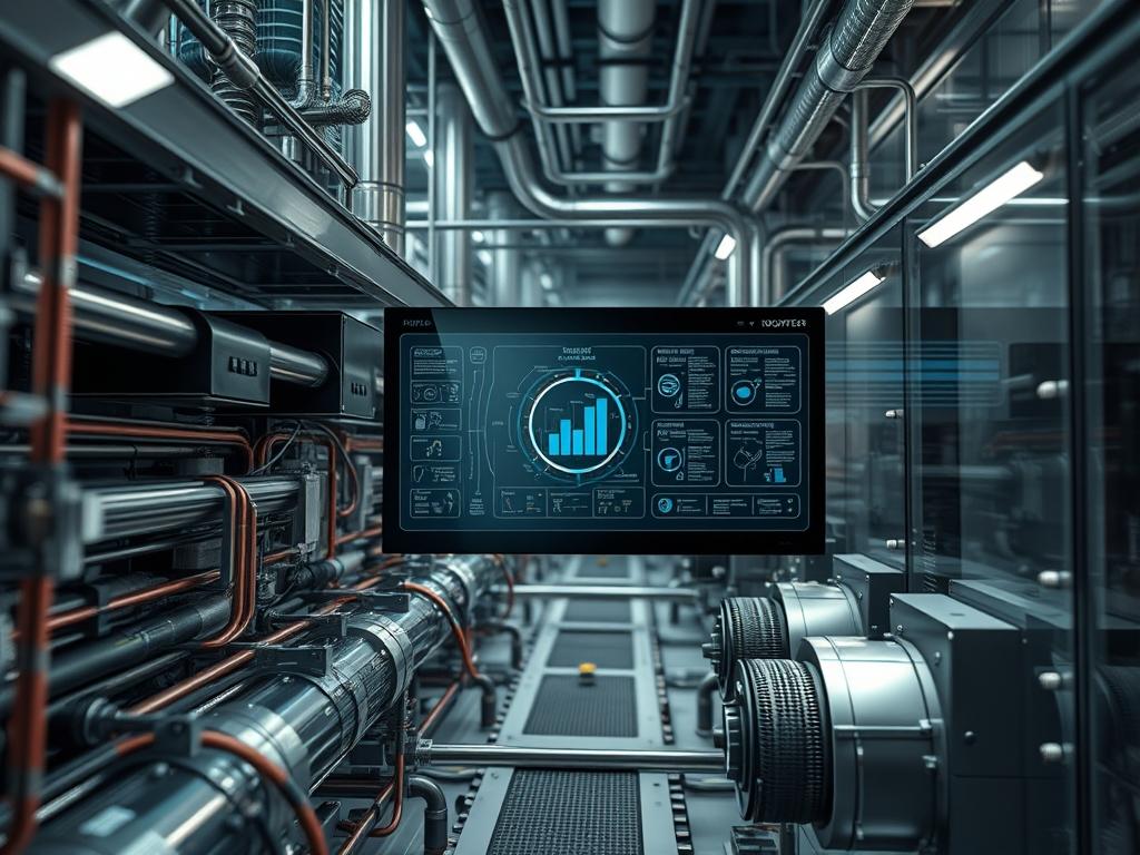
CO2 (R744) transcritical compression systems represent a fundamental shift in industrial thermal management and sustainable infrastructure. Within the broader technical stack of energy and data center cooling; these systems function as the primary heat rejection layer. Unlike traditional subcritical cycles where the refrigerant remains below the critical point; transcritical operations occur at pressures exceeding 73.8 bar and temperatures above 31.1 degrees Celsius. This phase behavior requires a unique engineering approach to manage supercritical fluids that do not follow standard condensation laws. The problem-solution context involves balancing high-side pressures; which can reach 120 bar; against ambient temperature fluctuations to maintain an optimal Coefficient of Performance (COP). In high-density cloud environments; these systems provide the thermal-inertia required to handle variable server loads. Successful implementation requires precise orchestration of high-pressure expansion valves and flash gas bypass logic to ensure that the system remains stable despite the lack of a traditional saturation curve in the gas cooler.
Technical Specifications
| Requirement | Default Port / Operating Range | Protocol / Standard | Impact Level (1-10) | Recommended Resources |
| :— | :— | :— | :— | :— |
| High-Side Pressure | 90 to 120 bar | ASME/PED | 10 | Grade 316L Steel |
| Low-Side Pressure | 25 to 45 bar | ASME/PED | 8 | Schedule 80 Copper/K65 |
| Control Interface | Modbus TCP (Port 502) | IEC 61131-3 | 9 | 1GHz CPU / 512MB RAM |
| Sensor Accuracy | +/- 0.5% Full Scale | 4-20mA / 0-10V | 7 | Shielded Twisted Pair |
| Thermal Stability | delta-T < 2K | IEEE 241 | 6 | High-Mass Heat Exchanger |
The Configuration Protocol
Environment Prerequisites:
System integration requires adherence to ASHRAE Safety Group A1 standards for R744. Ensure the physical site has sufficient ventilation to prevent CO2 concentration from exceeding the Short-Term Exposure Limit (STEL) of 30,000 ppm. Software dependencies include a real-time operating system (RTOS) or a hardened Linux kernel capable of handling high-frequency PID loops with minimal latency. Users must have root or administrator permissions on the industrial controller; such as a Carel pCO5+ or Danfoss AK-PC series; to modify high-level setpoints.
Section A: Implementation Logic:
The engineering design centers on the decoupling of pressure and temperature in the transcritical gas cooler. Because the refrigerant exists as a supercritical fluid; it does not condense at a constant temperature. Instead; the High Pressure Valve (HPV) must modulate the supercritical pressure based on the gas cooler exit temperature to maximize the enthalpy difference. This process is inherently non-linear. The control logic utilizes a lookup table or a polynomial equation to find the optimal pressure for the current ambient conditions. Below 25 degrees Celsius; the system reverts to subcritical mode for energy efficiency. The inclusion of a Flash Tank is a critical engineering requirement; it serves as a buffer to separate the liquid and vapor phases; ensuring that the liquid supplied to the evaporators is subcooled and the flash gas is bypassed directly to the high-pressure compressors or a dedicated parallel compressor. This encapsulation of the vapor phase reduces the workload on the main compression string.
Step-By-Step Execution
1. Initialize Controller Communication
Establish a connection to the primary controller using SSH or a serial console. Verify that the communication bus is active and that no packet-loss is detected between the sensors and the master logic unit.
System Note: Calling systemctl status industrial-monitor.service ensures the polling daemon is operational. This action stabilizes the communication layer before pressure is introduced.
2. Configure High Pressure Valve (HPV) Baselines
Navigate to the parameter directory at /etc/hvac/valves/hp_valve.conf. Set the initial PROPORTIONAL_GAIN and INTEGRAL_TIME for the transcritical loop.
System Note: Fine-tuning these variables prevents signal-attenuation in the feedback loop; which could lead to hardware-damaging pressure surges during a rapid shift in thermal-inertia.
3. Calibrate Pressure Transducers
Using a fluke-multimeter or a certified calibration-manifold; verify that the 4-20mA signals from the gas cooler outlet match the digital readouts in the controller software.
System Note: This ensures that the input-payload for the PID algorithm is accurate; preventing the system from exceeding the BURST_PRESSURE limits defined in the safety firmware.
4. Execute Dry-Run Solenoid Sequencing
Manually toggle the Liquid_Line_Solenoid and Bypass_Valve to confirm mechanical actuation.
System Note: Using the command set_output –id 0x04 –state ON triggers the relay via the logic-controller. This validates the electrical path and confirms that no signal-attenuation exists due to poor grounding.
5. Charge the System with R744
Slowly introduce CO2 into the system until the Flash_Tank_Pressure reaches 35 bar.
System Note: Incremental charging allows the system to settle and prevents thermal shock to the high-side components. This is an idempotent process where the final state is independent of the number of charging steps.
6. Synchronize VFD Compressor Speed
Set the Inverter_Frequency to match the minimum lubrication requirements of the compressors.
System Note: Proper VFD synchronization reduces the initial torque overhead and prevents a sudden drop in voltage across the local power grid.
Section B: Dependency Fault-Lines:
Software conflicts often arise when multiple PID loops compete for priority on a single-core CPU. If the Flash Gas Bypass Valve (FGBV) and the HPV attempt to update simultaneously; it can lead to concurrency issues and mechanical oscillation. Ensure that the task scheduler is configured for Fixed-Priority Preemptive Scheduling. On the mechanical side; poor insulation on the Liquid Line can cause premature flash gas formation; leading to a drop in system throughput and increased evaporator latency.
THE TROUBLESHOOTING MATRIX
Section C: Logs & Debugging:
Monitor the system logs at /var/log/hvac/thermal_errors.log for specific fault strings.
– Error Code E012: High Pressure Trip. Indicates that the gas cooler has exceeded 120 bar. Investigate the Gas_Cooler_Fan_Array for failure or the HPV for a stuck-closed state.
– Error Code E045: Oil Return Failure. Check the Oil_Separator level sensor. This often occurs when the mass flow rate is too low to carry oil through the vertical risers.
– Error Code E088: Communication Timeout. Signifies packet-loss on the Modbus branch. Inspect the termination resistors and shield grounding.
Visual cues are equally important. If the sight glass on the Flash Tank shows turbulence; it suggests that the HPV is hunting; which requires a reduction in the INTEGRAL_TIME variable. If frost appears on the compressor suction headers; the Superheat_Setpoint is likely too low; risking liquid slugging.
OPTIMIZATION & HARDENING
– Performance Tuning: To improve thermal-efficiency; implement a parallel compression strategy. Parallel compressors take suction directly from the Flash Tank at higher pressures; reducing the total compression ratio and increasing overall system throughput. Minimize latency in the expansion valve response by upgrading the stepper motor drivers to high-resolution units.
– Security Hardening: Industrial controllers should be isolated behind a dedicated firewall. Use iptables to restrict access to port 502 to only known administrative IP addresses. Disable unused services like Telnet or HTTP to minimize the attack surface of the control plane.
– Scaling Logic: As thermal loads increase; the system should utilize lead-lag logic to distribute the workload across multiple compressor racks. This ensures that the overhead of starting a large compressor is avoided unless strictly necessary. Maintain a Common_Suction_Header to balance pressures across different evaporative load zones; ensuring that no single unit becomes a bottleneck for the entire infrastructure.
THE ADMIN DESK
How do I handle a sudden loss of power?
A dedicated battery backup must power the HPV and FGBV to ensure they drive to the closed position during a blackout. This prevents high-pressure CO2 from migrating to the low-side components and causing a relief valve discharge.
What is the primary cause of low COP?
Operating the system at sub-optimal pressure during transcritical mode is the most common cause. Ensure the gas cooler controller is using the ambient-sensor feedback to adjust the high-side pressure according to the R744 transcritical curve.
How often should sensors be recalibrated?
Perform annual calibration on all pressure transducers. Drift in the high-pressure sensor can lead to inefficient operation or dangerous over-pressure events. Use a secondary NIST-traceable reference gauge for verification of current digital readouts.
Can I use standard refrigeration oil?
No; R744 requires specialized PAG (Polyalkylene Glycol) or POE (Polyolester) oils designed to maintain lubrication at high pressures and remain miscible at low temperatures. Standard mineral oils will fail and cause compressor seizure.
Why is my flash gas bypass valve always open?
This indicates high ambient temperatures or a lack of subcooling. The FGBV opens to maintain a stable Flash_Tank_Pressure. If it remains wide open; check for restricted airflow across the gas cooler or an overcharge of refrigerant.