
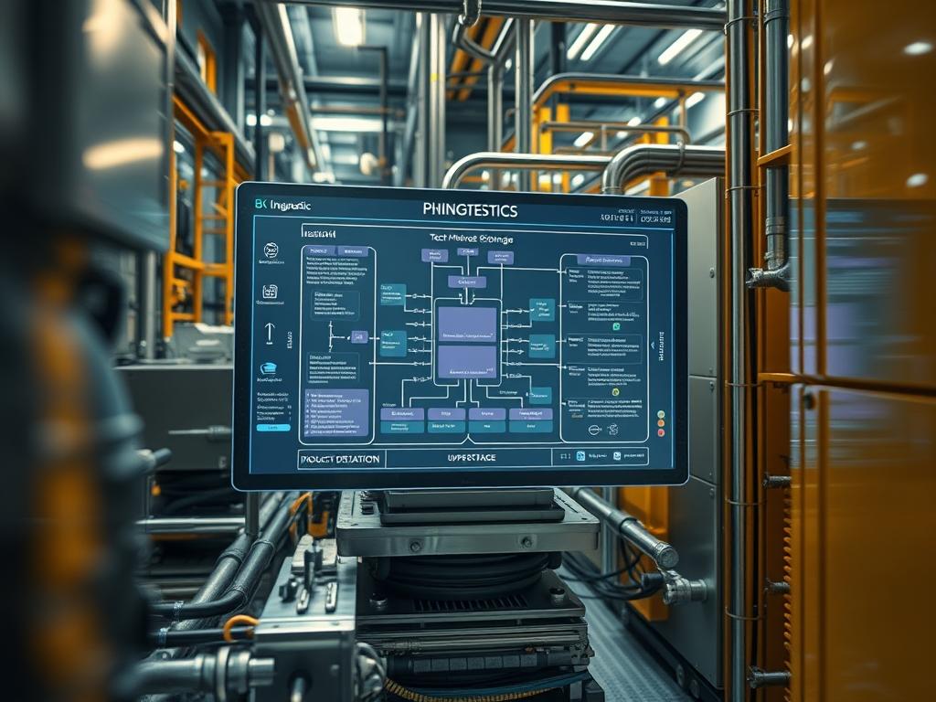
Thermal Storage Phase Change technology represents the frontier of density optimization within modern hyperscale data centers and high performance computing (HPC) environments. As electrical loads per rack exceed 50kW; traditional air cooling or even standard liquid cooling reaches a thermodynamic plateau. Thermal Storage Phase Change materials (PCMs) bridge this gap by utilizing the latent heat of fusion to absorb massive caloric loads at a constant temperature. This process decouples the cooling demand from the instantaneous heat generation of the CPU and GPU clusters; providing a buffer that stabilizes the thermal environment. Within the technical stack: specifically the physical layer and the facilities management plane: PCMs act as a passive thermal capacitor. By integrating these materials into heat exchangers or rear-door heat exchangers (RDHx); infrastructure architects can achieve higher compute density without corresponding increases in chiller capacity or water flow rates. This manual outlines the integration of salt hydrates and organic paraffins into the cooling loop to mitigate thermal-inertia and prevent critical hardware throttling.
Technical Specifications
| Requirement | Operating Range | Protocol/Standard | Impact Level | Resources |
| :— | :— | :— | :— | :— |
| Phase Transition Temp | 22C to 55C | ASHRAE TC 9.9 | 10 | Paraffin Grade A |
| Latent Heat Capacity | 180 to 260 kJ/kg | ASTM D4419 | 9 | High Density PCM |
| Thermal Conductivity | 0.2 to 5.0 W/mK | ISO 22007 | 7 | Graphite Matrix |
| Monitoring Interface | Port 502 (Modbus) | Modbus/TCP | 8 | 4-Core PLC |
| Storage Density | 120 to 200 MJ/m3 | IEEE 1150-1991 | 9 | Encapsulated Salts |
Configuration Protocol
Environment Prerequisites:
Successful deployment of Thermal Storage Phase Change systems requires strict adherence to environmental and software prerequisites. The primary dependency is the ASHRAE A1-A4 environmental envelope; ensuring that the facility water supply (FWS) temperature aligns with the PCM transition point. Hardware must include Programmable Logic Controllers (PLCs) with Modbus/TCP capabilities and a minimum of 8GB RAM to handle telemetry logs. Standard libraries such as OpenIPMI and lm-sensors must be installed on the host OS to correlate internal die temperature with external PCM state. Compliance with NEC Article 645 for Information Technology Equipment is mandatory for all physical installations.
Section A: Implementation Logic:
The logic governing Thermal Storage Phase Change is rooted in the “Why” of latent heat versus sensible heat. In a standard sensible heat system; every unit of energy added to the coolant results in a linear temperature rise. This creates a narrow margin before thermal-inertia leads to hardware shutdown. By introducing a PCM; the system utilizes the energy required to change the material’s physical state (solid to liquid) without increasing the temperature. This effectively “clips” the thermal peaks during high-load compute cycles. The Engineering design focuses on encapsulation: placing the PCM in direct proximity to the heat source or within the secondary cooling loop. This encapsulation ensures that the payload (the heat) is absorbed efficiently via conduction through a high-conductivity matrix: often expanded graphite: which minimizes thermal resistance and reduces signal-attenuation caused by temperature-induced impedance shifts in local networking hardware.
Step-By-Step Execution (H3)
Step 1: Baseline Telemetry Extraction
Initialize the system by capturing a 24-hour thermal baseline of the target rack or compute cluster. Run the command ipmitool -H
System Note: This action establishes the baseline thermal profile of the Baseboard Management Controller (BMC) hardware. It allows the Thermal Management Service to calibrate the PCM transition threshold against realworld idle and load states; ensuring the material does not stay permanently liquid or solid.
Step 2: PCM Encapsulation Integrity Verification
Before physical integration; inspect the PCM canisters or cooling plates for leakages or structural deformation. Use a fluke-multimeter with a thermocouple to verify the initial state of the material. If the material is in a solid state; verify that the Physical Thermal Resistance (Rth) is within the manufacturer’s specified tolerance of 0.05 K/W.
System Note: This step prevents fluid contamination within the rack. Leakage of salt hydrates can lead to rapid corrosion of the Motherboard PCB and critical ASIC components; while paraffin leaks present a significant fire hazard in high-voltage environments.
Step 3: Logic Controller Interface Setup
Connect the PCM-integrated heat exchanger to the local network via the RJ-45 Management Port. Access the PLC configuration via ssh admin@
System Note: Configuring the PLC via Modbus/TCP enables centralized control over the cooling pumps. By mapping the PCM state (Phase state: 0 for Solid; 1 for Liquid) to the pump speed; the system can intelligently ramp up flow only when the PCM has reached its maximum latent heat capacity; thereby reducing parasitic power loss.
Step 4: Daemon Initialization and Monitoring
Start the thermal monitoring daemon using systemctl start thermald. Verify the service status with systemctl status thermald to ensure it is correctly polling the linux-kernel thermal subsystem.
System Note: The thermald service monitors the D-Bus for thermal events. By synchronizing this with the PCM state; the kernel can delay P-state throttling of the CPU because the PCM provides an “extended thermal runway.” This significantly improves the throughput of long-running computational payloads.
Section B: Dependency Fault-Lines:
The primary failure point in Thermal Storage Phase Change systems is “Thermal Fatigue” or material degradation over thousands of cycles. If the PCM is not pure; it may undergo “Phase Segregation” where the chemical components separate; permanently altering the transition temperature. Another bottleneck is the “Thermal Resistance” at the interface. If the thermal paste or graphite pad between the compute node and the PCM-plate is improperly applied; the heat will not reach the storage medium fast enough: leading to a “Thermal Runaway” condition where the CPU overheats while the PCM remains solid.
THE TROUBLESHOOTING MATRIX (H3)
Section C: Logs & Debugging:
When a thermal discrepancy is detected; inspectors must immediately analyze the system logs located at /var/log/syslog and the specific PLC event logs at /opt/thermal/logs/event.log.
Error String: “CRITICAL: Phase Change Lag Detected”
This indicates that the rate of heat injection exceeds the PCM’s absorption rate. Check the thermal-conductivity of the graphite matrix. Use sensors to identify if specific cores are triggering the alarm.
Error String: “MODBUS_TIMEOUT_ERR”
This identifies a network failure between the thermal sensors and the logic controller. Verify the integrity of the Cat6e shielded cabling and check for high electromagnetic interference (EMI) near the pump motors.
Visual Inspection: Look for “frosting” or “sweating” on the exterior of the PCM canisters. This suggests that the transition temperature is set too low for the ambient humidity: potentially causing condensation and short-circuits. Adjust the transition point via the Modbus Register 40012 to a higher Celsius value.
OPTIMIZATION & HARDENING (H3)
Performance Tuning:
To maximize concurrency and throughput; the PID (Proportional-Integral-Derivative) loop within the PLC must be tuned. Reducing the “Hysteresis” value to 0.5C ensures a more rapid response to thermal spikes; though it may increase pump wear. To optimize thermal-inertia; architects should implement “Pre-Cooling” strategies: lower the PCM temperature to its solidus point during off-peak hours (low electricity cost) to maximize the available latent heat capacity for the subsequent peak compute cycle.
Security Hardening:
The thermal management network must be air-gapped or protected via strict iptables rules. Use chmod 600 /etc/thermal/config to restrict access to the configuration files. Since the cooling loop is a physical asset; implement physical failsafes: such as a “Normally Open” (NO) solenoid valve that defaults to maximum flow if the PLC loses power or the logic-controller service crashes. This ensures that the system fails in a “Safe-Cool” state.
Scaling Logic:
Scaling a Thermal Storage Phase Change architecture involves modularity. Instead of a single massive PCM reservoir; deploy “In-Rack” modules that can be hot-swapped. As the compute load grows from 50kW to 100kW; additional PCM modules can be slid into the rack chassis. This maintains a consistent footprint while doubling the thermal storage capacity; allowing for linear scaling of compute density without expanding the primary chilled water infrastructure.
THE ADMIN DESK (H3)
How do I verify if the PCM is fully charged?
Check the temperature readout via the PLC dashboard. If the temperature remains stable at the transition point (e.g., 28C) despite constant heat input; the PCM is in the latent phase and currently “charging” its energy storage.
What is the lifespan of organic paraffin PCMs?
High-grade paraffins are chemically stable for over 10,000 cycles. However; yearly inspections of the encapsulation seals are required to prevent oxidation; which can slightly shift the phase transition temperature over several years of continuous operation.
Can I mix different types of PCMs in one rack?
Mixing is not recommended unless the transition temperatures are tiered. Using a 25C PCM for primary cooling and a 45C PCM for emergency backup can provide a multi-stage thermal safety net against catastrophic cooling failures.
How does PCM integration affect packet-loss?
By stabilizing the temperature of optical transceivers and networking silicon; PCMs reduce the thermal drift that leads to “Signal Jitter.” This maintains high signal-to-noise ratios; effectively minimizing packet-loss and signal-attenuation in high-speed 400G and 800G fiber environments.
What happens if the PCM leaks?
Salt hydrates are conductive and corrosive; requiring immediate cleanup with deionized water. Organic paraffins are non-conductive but flammable: use Class B fire extinguishers. Always monitor the leak-detection-cable integrated into the secondary containment tray for immediate alerts.