
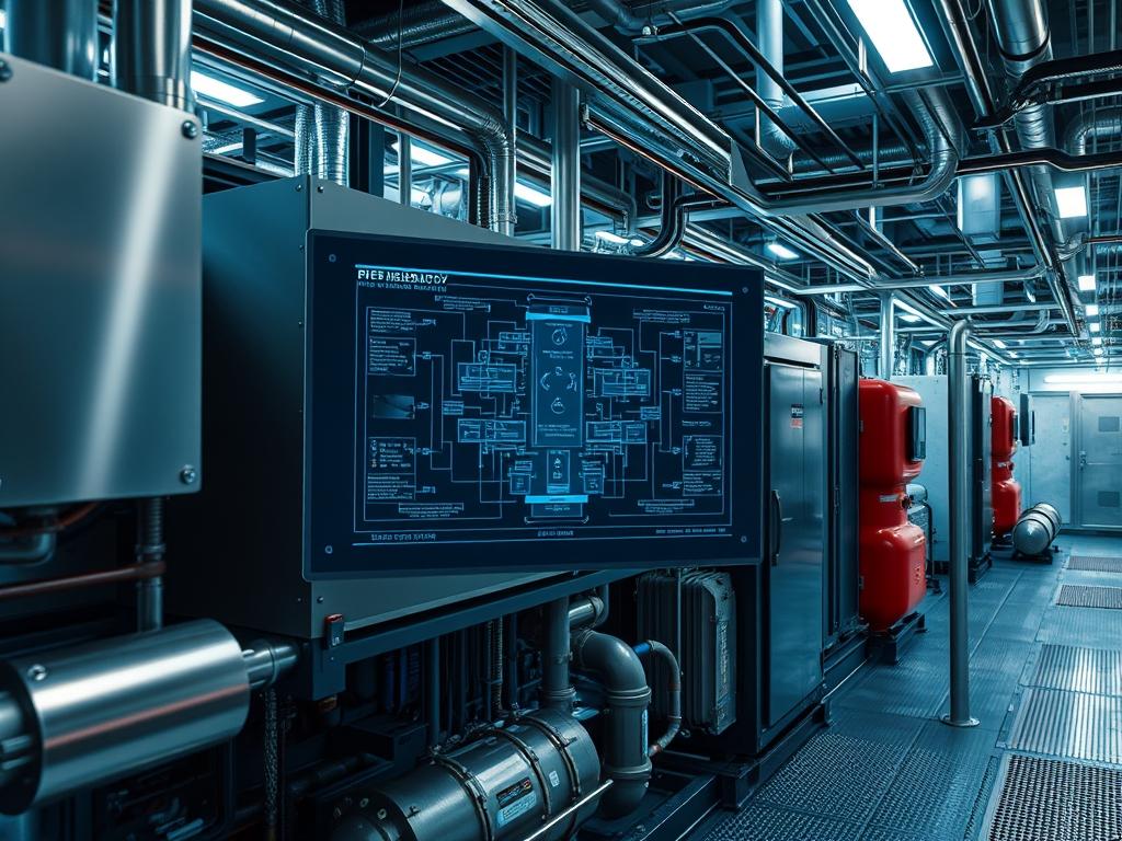
Industrial Refrigeration Troubleshooting represents the critical intersection of thermodynamic physics and automated control systems within high-capacity infrastructure. Unlike light commercial HVAC, industrial-scale systems utilize high-pressure ammonia (NH3), CO2, or complex hydrofluorocarbons to manage significant heat loads in cold storage, food processing, and chemical manufacturing. The troubleshooting process is not merely a mechanical repair cycle; it is a holistic diagnostic workflow that integrates mechanical integrity, electrical signal precision, and network communication stability. Within a modern technical stack, this falls under Energy and Facility Infrastructure, where the refrigeration system functions as a high-demand load managed by Supervisory Control and Data Acquisition (SCADA) systems. Effective troubleshooting requires an understanding of how mechanical anomalies, such as liquid slugging or oil logging, manifest as digital artifacts in PLC logs. The primary goal is to minimize downtime while maintaining thermal-inertia requirements, ensuring that the mass-flow throughput of the refrigerant remains consistent with the heat-rejection demands of the facility.
Technical Specifications
| Requirement | Default Operating Range | Protocol/Standard | Impact Level (1-10) | Recommended Resources |
| :— | :— | :— | :— | :— |
| Suction Pressure | 15 – 35 PSIG (Ammonia) | IIAR / ASME B31.5 | 9 | 32GB RAM SCADA Node |
| Discharge Temp | 160F – 240F | ASHRAE 15 | 8 | Titanium Grade Sensors |
| Control Logic | 4-20mA Current Loop | Modbus TCP/IP | 7 | Quad-Core PLC CPU |
| Power Quality | 460V / 3-Phase / 60Hz | IEEE 519 | 10 | VFD Harmonics Filter |
| Network Latency | < 50ms | Ethernet/IP | 6 | Cat6a Shielded Cable |
The Configuration Protocol
Environment Prerequisites:
Before initiating Industrial Refrigeration Troubleshooting, all technicians must verify compliance with IIAR-2 safety standards and NEC Class I, Division 2 requirements for hazardous environments. Software dependencies include a licensed installation of the Rockwell-Automation-Studio-5000 or Siemens-TIA-Portal for PLC interfacing. User permissions must be elevated to “Administrator” or “Service-Technician” levels within the SCADA interface to allow for manual override and PID tuning. Physical prerequisites involve a calibrated fluke-multimeter, ultrasonic-leak-detector, and a specialized refrigerant-manifold-gauge-set rated for the specific fluid in use.
Section A: Implementation Logic:
The engineering design of an industrial system relies on the principle of enthalpy exchange where the refrigerant serves as the medium for energy transport. The troubleshooting logic must follow the “Path of Least Resistance” theorem: identifying where energy or mass flow is impeded. We focus on the digital-to-mechanical feedback loop. Every mechanical action, such as a compressor-slide-valve movement, is preceded by a digital instruction and followed by a sensor verification. Discrepancies between the commanded state (the digital intent) and the actual state (the physical reality) indicate a failure. By isolating the layers of the system—mechanical, electrical, and logic—we can determine if a failure is the result of a physical component breakdown or a latency-induced error in the control stack.
Step-By-Step Execution
1. Verify Sensor Calibration and Signal Integrity
Begin by checking the raw input values from the RTD-Temperature-Probe and Pressure-Transducer. Use a fluke-multimeter to measure the voltage or current signal at the PLC-Input-Card.
System Note: This action confirms that the physical signal is not experiencing signal-attenuation or interference. If the hardware-measured value contradicts the SCADA readout, the issue resides in the signal-processing layer or the electrical termination.
2. Audit Compressor Staging and Concurrency
Access the Compressor-Control-Module via the HMI and review the staging logic. Ensure that the VFD-Frequency aligns with the required load and that no two high-start magnets are firing simultaneously.
System Note: Managing concurrency prevents voltage sags and protects the transformer from excessive in-rush current. The systemctl logs on the control server may show service restarts if the power quality is unstable.
3. Analyze the PID Loop Performance
Evaluate the “hunting” behavior of the Electric-Expansion-Valve (EEV). Adjust the Proportional, Integral, and Derivative gains within the PLC-Software to stabilize the superheat value.
System Note: High latency in sensor feedback leads to excessive valve modulation. Tuning the PID algorithm reduces the computational overhead of the processor and prevents liquid droplets from entering the compressor-suction-inlet.
4. Inspect the Oil Management Circuit
Check the oil-separator level and the differential pressure across the oil-filter. Inspect the solenoid-valve for the oil-return line to ensure it is not stuck in a closed state.
System Note: Proper oil throughput is required for both lubrication and sealing of the screw-compressor rotors. Failure in this subsystem will trigger a high-temperature alarm at the discharge-port due to friction.
5. Validate Evaporator Defrost Cycles
Review the defrost schedule and verify that the hot-gas-solenoid and suction-stop-valve are sequenced correctly in the logic controller. Use chmod style permission lockdowns on the defrost timer settings to prevent unauthorized tampering.
System Note: Incorrect defrost staging increases the thermal-inertia of the evaporator coils, leading to reduced heat transfer efficiency and increased energy consumption across the entire plant.
Section B: Dependency Fault-Lines:
Industrial Refrigeration Troubleshooting frequently unearths hidden dependencies. A common bottleneck is the contamination of the refrigerant charge with non-condensable gases (air), which increases discharge pressure and forces the compressor to work harder, leading to early mechanical fatigue. Another critical failure point is the communication link between the VFD and the PLC. If the Modbus TCP packet-loss exceeds 1 percent, the frequency drive may default to a “Last-State” or “Stop” configuration, disrupting the entire cooling process. Finally, mechanical bottlenecks like restricted suction-strainers can cause a drop in mass-flow throughput that no amount of software tuning can resolve.
THE TROUBLESHOOTING MATRIX
Section C: Logs & Debugging:
When a system failure occurs, the first point of reference is the SCADA-Event-Log located at /var/log/industrial/cooling_service.log or within the proprietary Alarms-and-Events database.
Error Code E004 (Communication Timeout): This indicates a network failure. Check the ethernet-switch and verify that the payload of the control packets is not being dropped due to a mismatched MTU-size or a faulty RJ45-connector.
Fault Code F101 (Low Suction Pressure): This typically points to a refrigerant shortage or a blocked TXV-orifice. Verify the physical liquid level in the high-pressure-receiver and ensure the solenoid is receiving its 24VDC signal.
Log String “PID-Saturation-Limit”: This software log indicates that the controller has reached its maximum output without achieving the setpoint. This is a classic indicator of an undersized physical component or a massive thermal load spike exceeding the system design.
Visually, if the HMI displays a jagged “sawtooth” pattern on the pressure graph, look for mechanical oscillation in the back-pressure-regulator. A flat line at the maximum scale usually suggests a broken sensor wire or a failed analog-to-digital-converter.
OPTIMIZATION & HARDENING
– Performance Tuning: To maximize thermal efficiency, implement a “Floating Head Pressure” strategy. This logic allows the PLC to lower the discharge pressure setpoint when ambient temperatures are low, reducing the energy consumption of the condenser-fans and compressors. This requires idempotent programming of the setpoint variables to ensure the system returns to a safe state after an override.
– Security Hardening: The control network must be isolated from the corporate WAN via a firewall using strict ACLs. Disable all unused services on the SCADA-Host. Ensure that physical fail-safe logic is hardwired: even if the PLC software crashes, high-pressure mechanical cutouts must remain capable of breaking the circuit to the compressor-motors.
– Scaling Logic: When expanding the facility, utilize a distributed I/O architecture. This reduces the signal-attenuation associated with long cable runs and allows for modular expansion without taxing the primary CPU of the main controller. Use encapsulation techniques in the data protocols to ensure that high-traffic data from new sensors does not interfere with critical safety-trip signals.
THE ADMIN DESK
Q: Why is my compressor cycling on the low-pressure cutout?
A: Check for a blocked suction-filter or insufficient refrigerant charge. Ensure the evaporator-fans are running. If the fans fail, the refrigerant cannot evaporate; this reduces suction pressure and triggers the safety-trip to prevent liquid slugging.
Q: How do I resolve frequent “VFD-Fault” errors on the HMI?
A: Inspect the VFD-Output-Filter and check for loose terminations at the motor. High electrical noise can cause packet-loss in the control signal. Ensure that the grounding-strap is properly bonded to the chassis to dissipate stray voltage.
Q: The SCADA displays NaN for temperature, but the sensor is new.
A: Check the I/O-Mapping in the PLC-Logic. A “Not a Number” (NaN) error often indicates a configuration mismatch where the software expects a 16-bit integer but receives a 32-bit float from the sensor.
Q: What prevents the system from restarting after an emergency stop?
A: The Safety-Relay must be manually reset. Check the PLC-Input-Status for the E-stop circuit. Industrial logic requires an idempotent reset signal; the system cannot resume operation until the physical safety chain is verified as closed.
Q: Why is the discharge temperature exceeding 250 degrees?
A: This indicates a high compression ratio or failing internal-bypass-valves. Inspect the oil-cooler for scaling. High temperatures lead to oil carbonization, which increases friction and creates a destructive feedback loop of heat and component wear.