
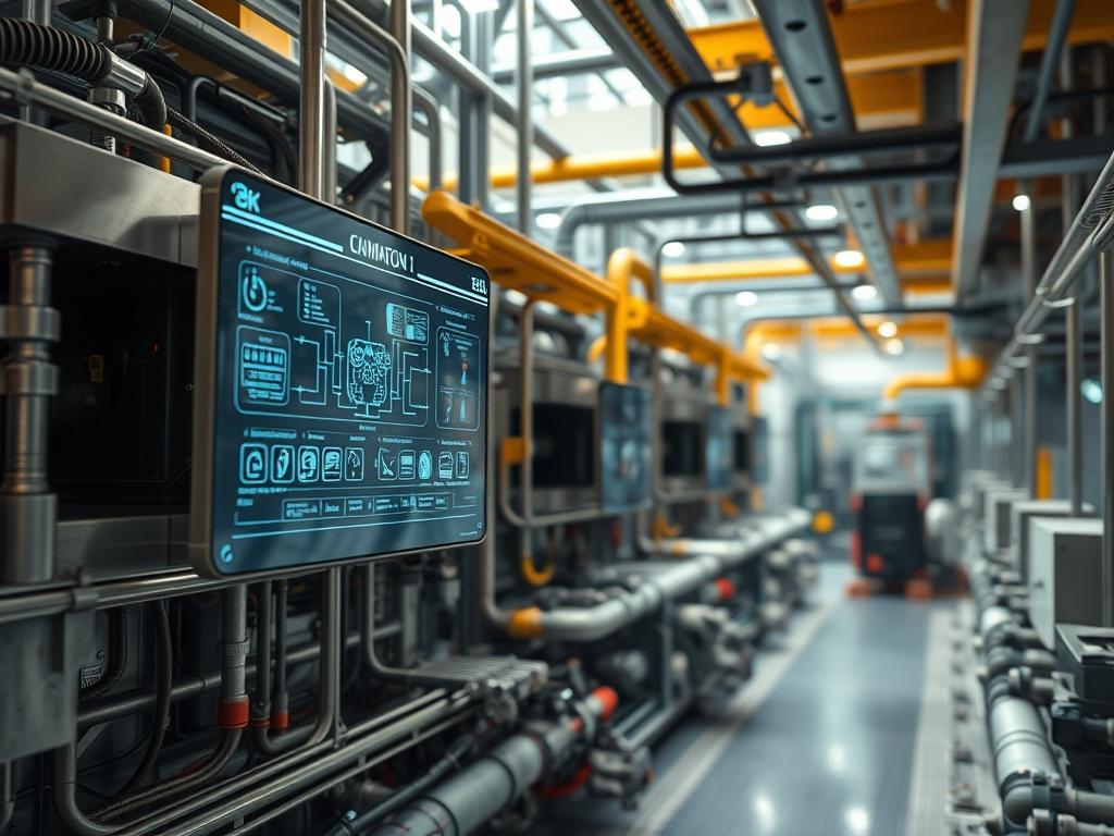
Oil Management in Ammonia Systems constitutes a foundational layer within the industrial thermal energy infrastructure. In an anhydrous ammonia (R-717) environment; the refrigerant and the lubricating oil are fundamentally immiscible. This chemical property necessitates a robust architectural stack to manage the lifecycle of the lubricant as it migrates from the high-side compression stage to the low-side evaporation stage. Failure to maintain oil purity impacts the entire system throughput; excessive oil migration leads to the coating of heat exchanger surfaces; creating a thermal-inertia barrier that degrades efficiency. The problem-solution context revolves around maximizing the efficiency of the coalescing filtration while ensuring that the low-pressure side of the circuit remains free of oil-rich payloads. This manual provides the protocol for ensuring that the lubrication remains localized to the compressor crankcase while maintaining high-purity refrigerant circulation across the network.
Technical Specifications (H3)
| Requirement | Operating Range | Protocol/Standard | Impact Level (1-10) | Recommended Resources |
| :— | :— | :— | :— | :— |
| Oil Viscosity | 68 to 100 cSt @ 40C | ISO VG 68/100 | 9 | PAO or Naphthenic Base |
| Discharge Temp | 71C to 115C | IIAR-2 Section 11 | 8 | Thermal Sensors (Type K) |
| Differential Pressure | 10 to 50 PSID | ANSI/IIAR 5-2019 | 7 | Coalescing Micro-Filters |
| Oil Separator Efficiency | 99.0% to 99.9% | ASHRAE 15 | 10 | Multistage Mesh/Fiber |
| Moisture Content | < 50 ppm | ASTM D1533 | 8 | Molecular Sieve Desiccant |
The Configuration Protocol (H3)
Environment Prerequisites:
Maintaining oil management systems requires adherence to specific industrial versionings and standards. The system must comply with ANSI/IIAR-2 for safe design and IIAR-6 for inspection and maintenance. Required hardware includes a Fluke-789 ProcessMeter for sensor calibration; API-618 compliant reciprocating or screw compressors; and a Logic-Controller (PLC) running firmware version 4.0 or higher. User permissions must be set to “Administrative/Service Level” to bypass standard interlocks during controlled oil-drainage sequences.
Section A: Implementation Logic:
The engineering design relies on the principle of mechanical coalescence. When the refrigerant gas carrying atomized oil particles enters the oil separator; it undergoes a velocity reduction. This reduction decreases the kinetic energy of the oil droplets; allowing them to impinge on filter media. The encapsulation of oil within the filter fibers leads to gravity-driven accumulation at the bottom of the vessel. From an architectural perspective; this process must be idempotent; the system should return to its optimal state regardless of how many times the separation cycle occurs. Effective management prevents signal-attenuation in ultrasonic level sensors by ensuring the liquid phase does not become a foam-heavy emulsion through high-velocity turbulence.
Step-By-Step Execution (H3)
1. Calibrate High-Pressure Float Switches (H3)
Verify the continuity and set-points of the oil level sensors using the Fluke-789 ProcessMeter. Adjust the resistor ladder to ensure that the PLC triggers a “High Level” alert at 75 percent capacity of the primary separator.
System Note: This action ensures that the throughput of the high-pressure gas remains unobstructed. If the float switch fails; the oil level will rise until it reaches the discharge line; leading to a catastrophic “slugging” event in the downstream condensers.
2. Configure Differential Pressure (DP) Thresholds (H3)
Access the Logic-Controller interface and navigate to the HMI_Alarm_Config module. Set the Oil_Filter_DP_High variable to 15 PSID for a warning and 25 PSID for a hard system shutdown.
System Note: The DP sensor monitors the health of the coalescing elements. High DP indicates filter saturation or carbonization; which increases the pump’s overhead and reduces the volumetric efficiency of the compressor.
3. Implement Low-Side Oil Recovery (H3)
Utilize the Regenerative Oil Still or an Automated Oil Return System (AORS). Open the supply valve V-102 and the return valve V-104 on the low-pressure accumulator to begin the distillation process.
System Note: By heating the oil-ammonia mixture; the ammonia evaporates and returns to the suction line. This prevents the thermal-inertia of the oil from insulating the evaporator tubes; which would otherwise cause a massive loss in cooling payload.
4. Purge Non-Condensable Gases (H3)
Connect the Purger-Logic to the top of the condenser and receiver. Execute the systemctl start r717-purge.service command on the control node to initiate the air-separation cycle.
System Note: Non-condensables increase discharge pressure; leading to higher oil temperatures. Excessive heat causes the oil to break down into varnish; which increases the friction latency across the compressor bearings.
5. Inspect Coalescing Elements (H3)
Shut down the compressor and perform a “Lock-Out Tag-Out” on the main breaker. Depressurize the Filter-Housing-B and extract the fiber elements. Use a micro-caliper to check for structural deformation of the filter core.
System Note: Maintaining the physical integrity of the filter prevents packet-loss of oil droplets into the discharge stream. Even a small breach in the filter media allows significant oil carryover to reach the expansion valves.
Section B: Dependency Fault-Lines:
Software and mechanical bottlenecks often arise at the interface between the Pressure Transducers and the Analog-to-Digital Converters of the PLC. If the sensor cable is and is not shielded; electromagnetic interference (EMI) can cause signal-attenuation; resulting in false oil-level readings. Another critical bottleneck is the solubility of ammonia in synthetic oils at high pressures. If the oil-seperator heater fails; the refrigerant will condense into the oil; lowering the viscosity and causing the compressor to seize due to inadequate lubrication film thickness.
THE TROUBLESHOOTING MATRIX (H3)
Section C: Logs & Debugging:
When a fault occurs; check the system logs located at /var/log/refrigeration/oil_mgmt.log. Look for specific error strings that indicate physical or logic failures.
- Error E04 (Low Oil Return): Indicates that the oil is trapped in the evaporator. Check the low-side suction traps for high liquid levels. Verify that the AORS solenoid is receiving a 24VDC signal from the PLC.
Error E12 (Separator Bypass): Indicates high velocity in the separator. This is often caused by a surge in concurrency* from multiple compressors starting simultaneously. Check the VFD ramp-up settings to smooth out the startup load.
- Fault Code F99 (High Filter DP): The coalescent media is blinded by impurities. Inspect the magnetic suction strainer for metallic debris; which may indicate internal compressor wear.
- Physical Cue (Frothing in Sight-Glass): This indicates high refrigerant concentration in the oil. Check the Crankcase-Heater for continuity using a multimeter. If the heater is functional; the system may be operating at a suction pressure below the oil’s vapor-pressure threshold.
OPTIMIZATION & HARDENING (H3)
– Performance Tuning: To optimize throughput; implement a variable-frequency drive (VFD) on the oil pump. By modulating pump speed based on the Differential-Pressure sensor data; you reduce parasitic power consumption. Use a Proportional-Integral-Derivative (PID) loop to maintain the oil temperature at exactly 20 degrees Celsius above the saturated discharge temperature to prevent refrigerant dilution.
– Security Hardening: Ensure that the Modbus/TCP or EtherNet/IP communication between the sensors and the PLC is isolated on a dedicated VLAN. Utilize firewall rules to block any inbound traffic on ports 502 or 44818 from outside the plant network. Physically lock the oil-drain valves with high-security seals to prevent unauthorized or accidental discharge of ammonia-laden oil.
– Scaling Logic: For large-scale facilities; utilize a distributed oil management architecture. Rather than a single central separator; install local sub-separators at each compressor group. This horizontal scaling allows for maintenance on one branch without affecting the total system latency. Use a master controller to synchronize the oil-return cycles; ensuring that the oil-return payload does not overwhelm the suction headers.
THE ADMIN DESK (H3)
FAQ 1: Why is oil temperature critical in R-717 systems?
Ammonia is not soluble in oil. If the temperature drops; the oil’s viscosity increases dramatically; leading to latency in reaching critical bearing surfaces and causing potential mechanical failure of the compressor assembly.
FAQ 2: How often should the coalescing filters be replaced?
Filters should be replaced when the differential pressure exceeds 15 PSID or annually. Continuous operation with saturated filters increases the overhead on the motor and leads to oil carryover into the evaporator.
FAQ 3: What causes oil foaming in the sight-glass?
Foaming is typically caused by rapid depressurization or a failed Crankcase-Heater. This causes the dissolved refrigerant to boil out of the oil rapidly; reducing the effective lubrication and risking oil-pump cavitation.
FAQ 4: Can I mix different types of ammonia compressor oils?
No; mixing Naphthenic and Synthetic PAO oils is forbidden. Incompatibility leads to sludge formation; which creates massive signal-attenuation in sensors and blocks the fine pores of the coalescing filtration stack.
FAQ 5: How does oil impact the system’s thermal-inertia?
Oil acts as an insulator on the internal surfaces of heat exchangers. Just a 1 mm film of oil can reduce heat transfer efficiency by 15 percent; significantly increasing the energy required for the same cooling throughput.