
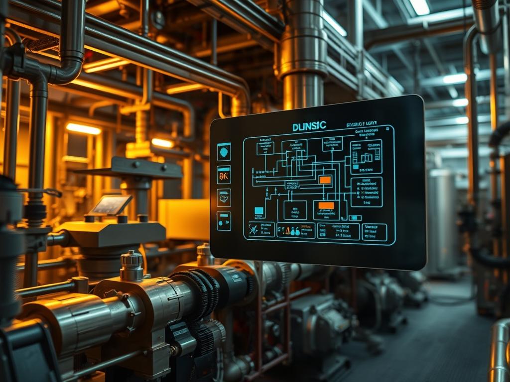
Biomass Boiler Combustion Logic represents the intersection of thermal dynamics and programmable process control. Within an industrial energy infrastructure: the combustion logic serves as the primary driver for converting solid organic payloads into stable thermal energy. It operates at the base of the technical stack: supporting high-level SCADA (Supervisory Control and Data Acquisition) systems and integrating with cloud-based efficiency monitoring via IIoT (Industrial Internet of Things) gateways. The core engineering challenge centers on fuel variability: biomass particles often exhibit inconsistent moisture content and bulk density: which introduces significant thermal-inertia into the system. Standard PID (Proportional-Integral-Derivative) controllers frequently fail when they cannot account for the latency between fuel delivery and heat release. This manual outlines the implementation of a feed-forward logic model. This model optimizes the stoichiometry of the furnace by reconciling fuel feed rates with oxygen trim data in real time: ensuring that the system maintains high throughput while minimizing unburnt carbon and flue gas emissions.
Technical Specifications
| Requirement | Operating Range | Protocol | Impact Level | Resources |
| :— | :— | :— | :— | :— |
| PLC Runtime | 10ms – 50ms Cycle | IEC 61131-3 | 10 | 1.2GHz CPU / 512MB RAM |
| O2 Probe | 0.5% to 21% O2 | 4-20mA Analog | 9 | Zirconia / High Temp |
| VFD Communication | 0Hz – 60Hz | Modbus TCP/IP | 8 | Cat6e / Shielded |
| Furnace Pressure | -20Pa to -50Pa | HART Protocol | 7 | Stainless Diaphragm |
| Fuel Moisture | 10% to 55% | RS-485 | 6 | Near-Infrared Sensor |
The Configuration Protocol
Environment Prerequisites:
Successful deployment requires a logic controller compliant with IEC 61131-3 standards. The hardware must be housed in a NEMA 4X or IP66 enclosure to mitigate dust ingress and thermal interference. Ensure that the Root User has administrative permissions for the SCADA Gateway and that all VFD (Variable Frequency Drive) units are flashed to the latest firmware to prevent communication jitter. Network resilience must be maintained via a redundant Ethernet/IP ring topology.
Section A: Implementation Logic:
The theoretical foundation of this configuration is the decoupling of the fuel feed rate from the instantaneous steam demand. Because solid fuel has high thermal-inertia: increasing the auger speed does not result in an immediate increase in heat. Instead: the logic uses a predictive “Look-Ahead” algorithm. By calculating the derivative of the steam pressure drop: the system anticipates demand before it manifests as a thermal deficit. The logic then utilizes encapsulation; the fuel feed sub-routine exists as an independent block that receives a “Calculated Burn Rate” payload from the master combustion module. This ensures that changes to the fuel type (e.g., shifting from wood chips to pelletized hulls) can be handled by updating a single variable without re-writing the entire codebase.
Step-By-Step Execution
Step 1: Calibrate Primary Air Baseline
System Note: This step establishes the oxygen-rich environment necessary for ignition and prevents the accumulation of combustible gases in the furnace. It affects the underlying kernel by setting the minimum safely allowable speed for the PA-Fan-01 service.
Execution: Access the PLC Debugger and navigate to the Air_Flow_Config block. Use a Fluke-773 to verify that the 4mA signal corresponds to the physical “Damper Closed” state. Set the MIN_FREQ variable to 25% of the motor rated capacity to ensure cooling air always flows across the Grate Bars.
Step 2: Establish Modbus Mapping for Fuel Augers
System Note: Mapping the registers allows the logic controller to command the physical hardware via an idempotent digital signal; ensuring that the command sent is the command received without signal-attenuation.
Execution: Open the Modbus_Config.xml file on the controller. Map the Auger_Speed_Command to Holding Register 40001. Use the systemctl restart mbus-service command to initialize the new mapping. Verify that the Payload reaches the VFD-Auger-01 by observing the “Target Frequency” on the local display.
Step 3: Configure the Moisture Compensation Loop
System Note: This action adjusts the “Weight-to-Volume” calculation of the fuel feed. It accounts for the overhead of evaporating water before combustion can occur: which prevents the firebox from cooling down during high-moisture fuel cycles.
Execution: Integrate the NIR-Sensor-01 input (Analog Input 4) into the Feed_Logic_v2 block. Define a multiplier variable: MOIST_COMP. If moisture exceeds 35%: the logic must automatically increase the Auger_RPM by a factor of 1.15 to maintain constant BTU throughput.
Step 4: Implement PID Auto-Tuning for O2 Trim
System Note: The O2 trim loop reduces the latency between detecting excess oxygen and adjusting the Secondary Air (SA) fans.
Execution: Set the PID_Proportional_Gain to 1.2 and the Integral_Time to 45 seconds. Use the Chmod 755 command on the local logic script folder to ensure the auto-tuner can write new gain values to the Config_Persistent directory. This provides the system with the ability to “learn” the combustion characteristics of the specific fuel batch.
Section B: Dependency Fault-Lines:
The most common point of failure is signal-attenuation in the 4-20mA loops: typically caused by improper grounding of shielded cables. If the O2-Sensor signal drifts: the logic will incorrectly starve the fire of air: leading to “Clinkering” or fused ash on the grate. Another critical bottleneck is the mechanical wear of the Auger Flighting. As the auger wears: the volumetric efficiency drops; the software may command 100% speed while the physical throughput remains at 70%. Monitoring the Amperage_Draw of the Auger_Motor is the primary method for detecting this mechanical slip.
THE TROUBLESHOOTING MATRIX
Section C: Logs & Debugging:
When the system detects a combustion anomaly: it generates an entry in the syslog located at /var/log/combustion/faults.log. Analysts should look for specific error strings that correlate to physical asset states.
1. Error: STOICH_LIMIT_EXCEEDED: This indicates that the fuel feed has reached its maximum allowable limit given the current air flow. Check for blockages in the Primary Air Duct or a failed SA-Fan bearing.
2. Error: MODBUS_TIMEOUT_NODE_04: This signals a packet-loss event between the PLC and the VFD. Inspect the RJ-45 termination points and ensure the logic-controller is not experiencing high CPU overhead that delays the polling cycle.
3. Error: THERMAL_INERTIA_OVERRUN: This occurs when the steam pressure continues to rise after the fuel feed has stopped. This suggests the Residual Fuel Bed is too deep. Recalibrate the Grate_Speed_Logic to increase ash removal frequency.
Visual cues from the HMI (Human Machine Interface) will show a “Red Waveform” when the oxygen pulse-width modulation (PWM) deviates more than 15% from the setpoint. Immediately verify the Zirconia Probe temperature; if it falls below 650C: the readings are invalid.
OPTIMIZATION & HARDENING
Performance Tuning: To maximize thermal efficiency: implement concurrency in the air damper movements. Instead of sequential adjustments: the Lead-Lag logic should move the ID-Fan and PA-Fan simultaneously. This reduces furnace pressure fluctuations and minimizes the “pumping” effect that wastes heat. Throughput can be further increased by reducing the PID Deadband to 0.1%: though this requires high-speed Servo-Actuators to avoid hunting.
Security Hardening: The combustion logic must be air-gapped from the facility’s guest network. Implement a strict Firewall Rule on the SCADA Gateway that only allows incoming traffic from specific MAC addresses associated with the engineer’s workstations. Use SSH keys for all remote terminal access to the PLC Kernel. Hard-wire an Emergency Stop (E-Stop) circuit that bypasses the software logic entirely to cut power to the fuel augers in the event of a “Runaway Thermal Event.”
Scaling Logic: As the facility expands to include multiple boiler cells: migrate the control architecture to a Master-Slave configuration. The Master PLC calculates the total facility load and distributes the “Load Percentage” payload to each individual Slave Boiler Controller. This prevents “Cycle Searching” where multiple boilers compete to stabilize the header pressure: which creates massive inefficiencies and unnecessary mechanical wear.
THE ADMIN DESK
How do I handle a sudden drop in fuel quality?
The logic should include a Fuel_Quality_Slew rate. Manually override the moisture variable in the HMI dashboard to 45%. This immediately adjusts the stoichiometric ratio and slows the Grate_Speed to allow for longer residence time in the furnace.
What is the fastest way to recover from a Modbus comm-loss?
Run the command systemctl restart modbus-bridge. If the link does not restore: check the 24VDC Power Supply to the RS-485 to Ethernet converter. Communication failures are often hardware-power issues rather than software bugs.
Why is my O2 trim oscillating?
This is likely a PID Tuning mismatch. Increase the Integral_Time (Ti) to slow down the controller response. Biomass systems have high latency; the controller must be “lazy” enough to wait for the fuel to ignite before making another adjustment.
How do I prevent the auger from jamming on oversized fuel?
Enable the Auto-Reverse logic. If the Auger_Motor_Amps exceeds 150% of the rating for more than 2 seconds: the PLC should reverse the motor for 5 seconds before attempting to feed forward again. This clears most physical obstructions automatically.