
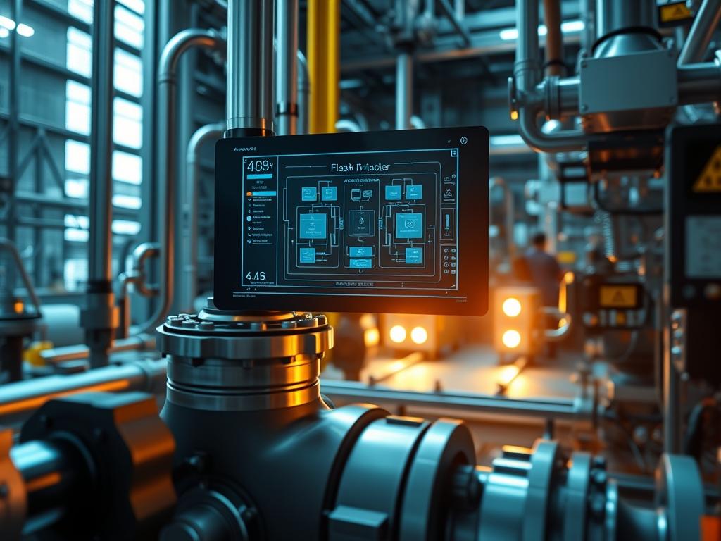
Optimizing the thermal cycle within industrial refrigeration and high density liquid cooling environments requires a nuanced approach to phase change management. The Flash Gas Bypass Valve Setup serves as a critical stabilization mechanism for evaporators operating under variable thermal loads. In a standard refrigeration loop, high pressure liquid experiences a partial phase change as it passes through the expansion device, resulting in a mixture of liquid and “flash gas.” This flash gas contributes zero net cooling capacity yet occupies significant internal volume within the evaporator tubes. This leads to increased pressure drop and reduced heat transfer efficiency. By implementing a Flash Gas Bypass Valve Setup, the system diverts this non-productive vapor directly to the suction line or the evaporator outlet. This architectural shift ensures that the evaporator receives a higher quality of liquid refrigerant, thereby maximizing the effective surface area available for latent heat exchange. In the context of large scale thermal management for data centers or energy infrastructure, this setup reduces compressor overhead and mitigates the risk of liquid slugging, which is essential for maintaining high availability and long term asset integrity.
TECHNICAL SPECIFICATIONS
| Requirement | Default Port/Operating Range | Protocol/Standard | Impact Level (1-10) | Recommended Resources |
| :— | :— | :— | :— | :— |
| Pressure Transducer | 0 to 500 PSIG | 4-20mA / Modbus RTU | 9 | 316 Stainless Steel |
| Bypass Solenoid | 24VDC / 110VAC | PWM Control | 8 | High-Flow Orifice |
| Logic Controller | 100ms Scan Rate | IEEE 802.3 / BACnet | 7 | Quad-Core / 2GB RAM |
| Thermal Sensors | -50C to +150C | PT1000 Class A | 9 | Shielded Twisted Pair |
| Piping Manifold | 5/8″ to 2-1/8″ OD | ASME B31.5 | 6 | Type L Copper |
THE CONFIGURATION PROTOCOL
Environment Prerequisites:
1. Licensed installation of RSLogix or CODESYS for logic control implementation.
2. Minimum hardware revision of the Electronic Expansion Valve (EEV) controller to support secondary bypass logic.
3. Integration with a Supervisory Control and Data Acquisition (SCADA) system for real-time telemetry.
4. Physical clearance for a secondary bypass line parallel to the primary expansion header.
5. All pressure vessels must comply with ASHRAE 15 and UL 60335-2-89 safety standards.
Section A: Implementation Logic:
The Flash Gas Bypass Valve Setup operates on the principle of reducing thermal-inertia by decoupling gas management from liquid metering. In conventional systems, the expansion valve must handle a high volume of gas-liquid mixture, which increases the latency of the cooling response when setpoints are adjusted. By introducing a bypass, we utilize an idempotent control loop: for every unit of pressure increase detected at the receiver outlet, the bypass valve adjusts its orifice to maintain a constant gas-to-liquid ratio entering the evaporator. This reduces the overhead on the compressor by ensuring that the suction gas remains at a consistent density. Furthermore, this configuration enhances the throughput of the evaporator by preventing “dry out” at the tail end of the coils, as the liquid remains in a more saturated state throughout the length of the heat exchanger.
Step-By-Step Execution
1. Primary Bypass Line Integration
Install the Bypass Solenoid Valve in a dedicated line connecting the top of the Flash Tank or Liquid Receiver directly to the suction header.
System Note: This physical routing allows gaseous refrigerant to bypass the expansion device entirely; it reduces the volume of vapor that the evaporator must “process” and significantly lowers the internal pressure drop.
2. Sensor Array Deployment
Mount the Pressure Transducers and PT1000 Thermal Sensors at the inlet of the Electronic Expansion Valve and the outlet of the Suction Line. Use Shielded Twisted Pair cabling to prevent signal-attenuation in high EMI environments.
System Note: Accurate sensor placement is vital for calculating real-time sub-cooling and superheat; the controller uses these variables to determine the payload of flash gas available for diversion.
3. Logic Controller I/O Mapping
Map the 4-20mA Output Signal from the controller to the Bypass Valve Actuator. Ensure the I/O Address for the Pressure Transducer is correctly identified in the PLC Tag Database.
System Note: Correct mapping ensures that the concurrency of the primary expansion valve movements and the bypass valve adjustments are synchronized; this prevents “hunting” or oscillations in the system pressure.
4. PID Loop Configuration
Define the Proportional, Integral, and Derivative gains within the Control Kernel. Set the Sampling Rate to 250ms to ensure the system can react to rapid load shifts without overshooting the setpoint.
System Note: Fine-tuning the PID coefficients minimizes latency in the response curve; an optimized loop maintains the evaporator at its maximum heat transfer coefficient regardless of ambient temperature swings.
5. Communication Protocol Activation
Configure the Modbus/IP or BACnet gateway to broadcast valve position and pressure data to the Management Console. Set the Heatbeat Interval to 5 seconds to monitor for packet-loss.
System Note: Continuous telemetry allows the audit team to verify the idempotent nature of the control logic and ensures that the system is operating within its designed efficiency envelope.
Section B: Dependency Fault-Lines:
The most frequent point of failure in a Flash Gas Bypass Valve Setup is the mismatch between valve sizing and terminal load. If the bypass valve is oversized, it can cause a rapid drop in high-side pressure, leading to a loss of sub-cooling. This trigger-effect causes the primary EEV to cycle rapidly, creating a throughput bottleneck. Another bottleneck is the accumulation of compressor oil in the bypass line; without a proper Oil Separator and return logic, the thermal-inertia of the evaporator increases because of the oil film coating the internal tube walls. Ensure that the Oil Return Solenoid is pulsed during every idempotent cycle to maintain internal hygiene.
THE TROUBLESHOOTING MATRIX
Section C: Logs & Debugging:
When a failure occurs, the first point of inspection should be the System Error Log located at /var/log/hvac_control/bypass_errors.log.
Error Code E-041 (Pressure Imbalance): Indicates a discrepancy between the High-Side Transducer and the Manual Gauge Readout. This usually points to signal-attenuation* or a failed sensor diaphragm.
- Error Code E-112 (Valve Latency): The Bypass Valve Actuator is not reaching its commanded position within the 500ms window. Check the 24VDC Power Supply for voltage drop and inspect the valve stem for debris.
Error Code E-909 (Modbus Timeout): This indicates packet-loss* on the communication bus. Verify the integrity of the RJ45 Connections and ensure that the Terminating Resistors are correctly installed on the RS-485 run.
Physical cues also provide critical data. If frost is visible on the Bypass Line, the valve is leaking or stuck open, which causes the suction gas to overheat and reduces the overall payload of the cooling cycle. Use a Fluke Multimeter to check the mA loop stability; erratic readings often suggest a grounding issue or interference from a nearby Variable Frequency Drive (VFD).
OPTIMIZATION & HARDENING
To achieve maximum performance, the Flash Gas Bypass Valve Setup must be hardened against environmental and electrical fluctuations.
Performance Tuning:
Adjust the Minimum Opening Percentage of the bypass valve to 5 percent. This ensures a constant, albeit small, bleed of gas which prevents the valve from “sticking” in the closed position during low-load states. This technique improves the throughput of the system during a sudden ramp up in thermal load. Furthermore, implementing a Feed-Forward Control logic allows the system to preemptively open the bypass valve when a secondary compressor starts, reducing the initial pressure spike.
Security Hardening:
In networked configurations, the Logic Controller must be isolated from the public internet via a Hardware Firewall. All Modbus traffic should be restricted to a specific VLAN. Disable any unused services like Telnet or FTP on the Gateway Module. Physical hardening includes the use of Braided Stainless Steel Sleeving for all sensor wires to prevent physical damage or electromagnetic interference that could lead to signal-attenuation.
Scaling Logic:
In a multi-evaporator rack system, the bypass setup should be centralized at the Main Header rather than localized at each evaporator. This centralized approach reduces the Part Count and simplifies the encapsulation of the refrigerant logic. As the system scales, use a Master-Slave Controller Configuration where the master node calculates the total required bypass flow and distributes the work-order to individual slave valves. This ensures that concurrency is maintained across the entire infrastructure, preventing pressure surges in one branch from affecting the others.
THE ADMIN DESK
How do I verify if the bypass valve is sized correctly?
Monitor the High-Side Pressure during a full-load to part-load transition. If the pressure drops by more than 15 percent in under 30 seconds, the valve is likely oversized for the current throughput requirements.
What is the impact of flash gas on evaporator capacity?
Flash gas can reduce effective capacity by 20 to 35 percent. It displaces liquid refrigerant and creates a high velocity vapor stream that inhibits the formation of a stable liquid film on the tube walls.
How does signal shadowing affect the PID loop?
Signal-attenuation from unshielded cables introduces noise into the 4-20mA loop. This causes the controller to perceive phantom pressure fluctuations, leading to unstable valve movements and increased overhead for the actuator motors.
Can this setup prevent liquid slugging in the compressor?
Yes. By diverting gas and keeping the evaporator efficiently flooded with high-quality liquid, it allows for more precise superheat control at the suction header. This ensures only dry vapor reaches the compressor inlet.
Is there a minimum sub-cooling requirement for this setup?
Yes; a minimum of 5 degrees Kelvin of sub-cooling is recommended. Insufficient sub-cooling at the inlet of the FGBV can cause the valve to hunt as it struggles to distinguish between liquid and vapor phases.